Liquid cooling in data centers
Cooling Systems in Data Centers: State of Art and Emerging Technologies
- This topic has 0 replies, 1 voice, and was last updated 1 month, 1 week ago by .
Answers
-
February 16, 2026 at 7:21 pm by Oleksandr Dannyk
Alfonso Capozzoli, Giulio Primiceri (Politecnico di Torino, Corso Duca degli Abruzzi 24, Torino 10129, Italy)
Abstract
The growing number, size, complexity and energy density of data centers due to increasing demand for storage, networking and computation bring a considerable energy challenge. Several measures to improve energy efficiency are being studied, not only to allow a supportable industry growth but also to reduce operational costs. Cooling energy consumption constitutes a large portion of the total consumption of data centers, which can account up to 40% in the case of inefficient cooling systems. In this paper a critical discussion on existing and emerging technologies for data center cooling systems was carried out. Fundamental aspects concerning advantages and drawbacks of each examined cooling system were discussed. Moreover a critical analysis on next future technology solutions for obtaining high energy efficiency data center is performed.
Keywords: Data center; Cooling technologies.
1. Introduction
The increasing demand for data processing in recent years along with advances in computer and electronic technology produced a rapid growth in the data center sector. The growth in Data Center (DC) number and power densities is leading to an increase in energy demand. According to [1], the total electricity used in data center doubled between 2000 and 2005 and grew by 56% between 2005 and 2010. Moreover, in 2010 the data center sector
was accountable for 1.3% of worldwide electricity consumption and 2% of US electricity consumption [1]. The energy consumption is estimated to increase by 15-20% per year in the next future [2]. This large energy consumption is mainly due to IT power and cooling requirement, with lighting, air movement, power distribution and others requirements that account for the remaining share. A cooling system is vital in order to maintain IT equipment working in a safe and reliable manner and it can account for up to 40% of the total energy consumption in a DC. Hence, the improvement of cooling system efficiency represents a great opportunity for energy and cost savings in DC. Most data centers use air-cooled systems for the heat removal process. Nevertheless data center industry is going to approach and exceed the heat removal capacity of air. Hence new cooling solutions and technologies, such as fully immersed direct liquid-cooled, micro-channel single-phase flow or micro-channel two-phase flow, should be taken into account. In this paper a critical discussion on the most promising cooling systems technologies is provided. Moreover a critical discussion on the next future technology solutions is performed.1.1. Environmental requirements and thermal load in data centers
A data center should be adequately cooled because heat dissipation is a crucial factor to be considered for availability and reliability of the IT equipment. Advances in the microprocessor industry result in a continuously growing number of transistor for chip and clock rates, which in turn cause a dramatically rise of heat dissipation density. High heat density can cause high junction temperatures which affect the reliability of IT components. In
fact, the main cause of component failure is high temperature [4]. A cooling system has to be able to achieve a full environmental control, including air temperature, humidity and pollution concentration. In order to design a cooling system capable of achieving this tasks, environmental limit values were defined for assuring a proper work of IT equipment in operating conditions. The power demand of a server, which can be considered the smallest processing unit in a data center, can vary with the actual work done, but even when the server works at or below 20% of its capacity, the power consumption is between the 60-100% of the maximum [2]. Furthermore, the consumption may vary with different types of servers (i.e. single or dual socket processor, or blade) and manufacturers. Nevertheless, in literature various researchers estimate an average power demand of 400 W for a standard server and 300W for a blade server [2, 3, and 5]. Therefore power density per rack can achieve 20 kW or above. Moreover a full length
rack can be filled with 64 or more blade servers, depending on the chassis dimensions, reaching higher power demand and hence thermal load. This notwithstanding, the average power density per rack reported by the Emerson network power in 2014 was of 6.7 kW per rack for North America data centers. The server is composed of different elements, such as the microprocessors, DIMMs, I/O devices, mass storage and auxiliary components. In order to avoid failure it is important to maintain these components within proper temperature limits. For instance, as pointed out in [2, 3], most researchers consider 85°C the maximum allowable junction temperature to avoid malfunctions.
The same limit is considered for DIMMs, while for storage devices the temperature limit is about 45°C. Humidity control is also important for the correct operation of IT equipment. Condensation and electrostatic discharge can occur with respectively high and low indoor relative humidity. The reliability of IT equipment could also be affected by dust, gaseous and particulate contamination, especially where a direct fresh air economizer mode is employed in
locations with high pollutants concentration, such as an industrial area. Hence an effective filtration system is needed. In order to maintain the IT equipment temperature within the limits and to help data center operators to achieve reliability and energy efficiency in their facility, ASHRAE published “Thermal guidelines for data processing environments”[6]. It provides appropriate environmental conditions for minimizing failure risks while achieving energy efficiency. The environmental conditions refer to the temperature and relative humidity (RH) of the air at the inlet of IT equipment and are provided for different classes according to the type of the equipment. A dry bulb temperature between 18°C and 27°C and humidity within a dew point temperature of 5.5°C, a relative humidity of 60% and dew point temperature of 15°C are the recommended operating environmental conditions for Class A1 to A4. Over the years the TC 9.9 updated the guidelines, adding new classes and extending the temperature and humidity ranges in order to achieve higher level of efficiency (allowing operators to use economizer modes for a higher number of hours). In fact, as stated in [7], the energy saving generated by the use of free cooling is reduced by 2.8-8.5% for every 2°C decrease in indoor temperature, depending on the climate zone.2. Cooling system overview
Practically all the electrical power required in a data center is converted into heat, which has to be removed by a proper cooling system. The most suitable cooling solution should be designed, depending on the design criteria, to obtain a high energy efficiency, low cost and reliability. A cooling system should be designed to cover the worst case scenario, although most servers generally work at much lower capacity than 100%. The control and prediction
of temperature rising during a utility power outage is an important aspect for cooling system design. Air-cooled systems represent the backbone of data center cooling systems; they are evolving over the years to cope with the advance in the IT equipment. The evolution of air-cooled system is going towards localized cooling units and physical separation of the airstream within the data center, in order to support the rising power densities. On the
other hand, liquid-cooled systems are becoming promising and emergent solutions for cooling high power density data centers. Today the IT equipment is reaching power densities that in some cases justify the liquid-cooled solutions; moreover, if the IT industry grows with the same trend of the last years, air-cooled systems will not be able to accomplish the cooling process. Despite the differences among the various cooling systems, there are some
aspects that allow a general description and categorization [8]. The bulk cooling capacity is provided by the mechanical equipment: different systems such as chilled water systems, direct expansion air cooled systems and direct expansion glycol cooled systems are used. The heat rejection represents the last step in the heat removal process: cooling towers and dry coolers are the most common heat rejection systems for the data center industry.
The terminal cooling equipment has the task of distributing the cooling capacity via air, in air-cooled systems, or via liquid, in liquid-cooled system. Furthermore, the use of economizer mode is vital to achieve a higher energy efficiency and energy savings in DCs.2.1. Heat rejection system and mechanical equipment
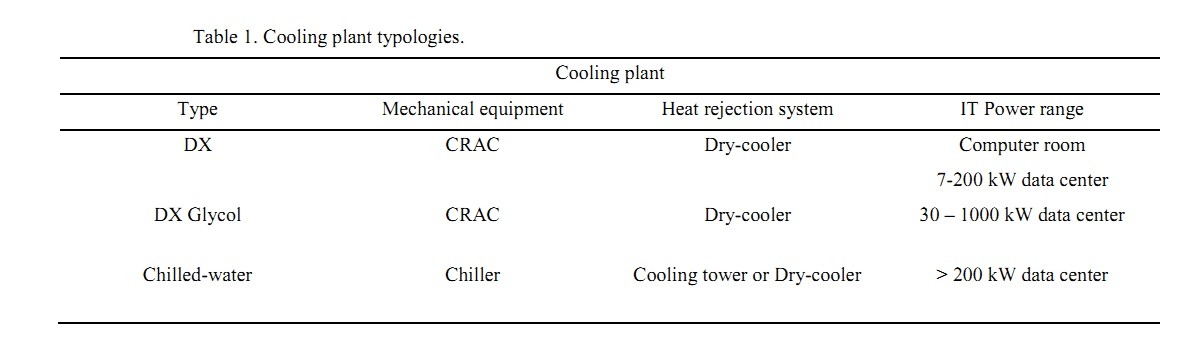
The cooling plant of a data center consists of an active equipment and a heat rejection system. The mechanical equipment can be a direct expansion system (DX) or a chiller. DX systems consist of a Computer Room Air Conditioner (CRAC) and an air-cooled condenser as heat rejection system. In this case the mechanical equipment is also included in the terminal cooling equipment. The short piping length and the need of a condenser for each
CRAC represent the main disadvantage of this system. This solution has a lower capital cost and it is easy to maintain. It is usually used in computer room and data center from 7 up to 200 kW of IT power [9].
An alternative solution for the heat rejection is a glycol-cooled system. In this case a glycol mixture is used as heat transfer fluid from the CRAC to dry cooler. The glycol piping can run a much longer length and a dry cooler can serve multiple CRACs. This solution can be used in data centers form 30 to 1000 kW [9]. In chilled-water systems, a chiller provides cold water to the Computer Room Air Handler (CRAH). In this system the terminal equipment assures only the IT temperature and humidity control. The heat rejection system vary upon the type of chiller, i.e. water-cooled chiller, glycol-cooled chiller or air-cooled chiller: cooling tower for liquid chiller and dry cooler for the other types. The efficiency of a chilled-water system improves with the increase of data center capacity. Chilled-water systems have the highest capital cost for data center below 100 kW of IT power, and are usually used in installation above 200 kW of IT power [9]. Table 1 summarized the cooling plant typologies.2.2. Terminal Cooling Equipment
2.2.1. Air-Cooled systems
The terminal cooling equipment should provide air with the right cooling capacity and a properly distribution. As
stated in [10], there are several parameters that could influence the cooling efficiency, such as ceiling height, where hot air stratification may occur, raised floor/dropped ceiling height, which is important for achieving a correct air distribution between the IT equipment, and airflow direction in the room. Two major air distribution problem have been identify in data center, by-pass air and recirculation air [11]. Re-circulation air occurs when airflow to the
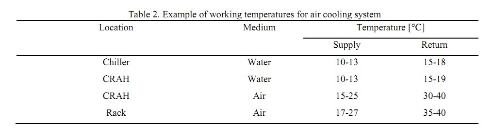
equipment is not sufficient and part of the hot air is re-circulated, which results in a considerable difference between inlet temperature at the bottom and the top of the rack can occurs [10]. By-pass of the cold air occurs due to a high flow rate or leaks through the cold air path. In this case, part of the cold air stream skips directly from the cold air supply to the exhaust air without contributing to the cooling process [12]. This poor air management results in a low cooling efficiency and generates a vicious cycle of rising local temperature [13]. In fact, as pointed out in [14] about one rack in ten works with a temperature above the standard recommendations and the majority of hot spots occur in data centers with light load, indicating that the main cause of hot spots is a poor air management. In order to prevent hot spots, usually the temperature of the cooling system is set below the IT requirements [15]. Table 2 shows an example of operating temperature for an air-cooled system from chiller to rack. As pointed out in [16], this solution is effective for power density of about 1-2 kW per rack. The first step to improve efficiency is the employment of effective aisles containment. The containment of the hot (or cold) aisles is one of the most effective and less expensive strategies to improve energy efficiency for a data center. The containment allows the physical separation of the air streams, hence avoiding problems of recirculation or bypass: in this way air at higher temperature can be supplied, thus increasing cooling efficiency. A theoretical analysis of Niemann et al. [15] shows that between cold aisle and hot aisle containment the latter (HACS) is the best solution. It is also convenient to localize the terminal cooling equipment closer to the source in order to achieve a better air flow distribution. In this way it is possible to categorize the air-cooled system in Room based cooling, In-row cooling, Rack based cooling.
The room, row or rack cooling solutions provide the same amount of cooling capacity, but are characterized by different methods of distributing the air. As a consequence they are characterized by different cooling efficiency and capital cost. In-row and rack-based cooling systems have in fact the advantage of a shorter airflow path allowing a reduction of the fan power requirement and thus an increased efficiency. Moreover they produce a mitigation or elimination of recirculation phenomena. Different solutions can support different power density. Rack-based cooling systems support power density up to 50 kW per rack [16]. On the other hand, rack-based and in-row cooling presents higher capital costs than room option due to a higher number of cooling unit and piping.
The in-row cooling solution can be achieved placing the terminal cooling equipment between the racks oroverhead. The rack-based cooling solution can have a closed or open design. In the closed design the servers and the terminal cooling equipment are accommodated within the closed rack envelope and thus the airflow is completely isolated from the rest of the data center [16]. The open design on the contrary, as proposed by Almoli et al. [17], is
characterized by a rear door heat exchanger which shares with a room-based solution the task of cooling the IT equipment. The rear door can be active, if it has dedicated fans to control the airflow through the back door heat exchanger, or passive, if the server fans drive the airflow through the rear door. These solutions can be implemented in existing data center, allowing the use for high density racks, isolating them from the room-based cooling system.
In-row cooling is recommend for existing data center with high density server racks, from 5 kW per rack and above, whereas rack-based cooling solution are suggested for higher density racks.2.2.2. Liquid-cooled systems
When DCs have a high power density equipment, air-cooled systems might not be the best solution in terms of efficiency and reliability. Therefore different cooling technologies should be employed in such cases, like liquid-cooled systems, that are capable of supporting high density power and offer a wide range of advantages. The main advantage, as pointed out in [18], is the higher heat transfer capacity per unit, which allows working with lower
temperature difference between the CPU and the coolant. Moreover, this solution eliminates two low efficiency steps of air-cooled systems, heat-sink-to-air and air-to-coolant heat transfer. Hence, a decrease in the system thermal resistance and an increase in energy efficiency can be obtained [19]. Higher inlet temperatures can potentially eliminate the need of active equipment for the heat rejection, and also open up the possibility of heat reuse.
Liquid-cooled systems can be constructed using micro-channels flow and cold-plate heat exchangers in direct contact with some components, such CPUs and DIMMs, as studied by Zimmermann et al. [20] or by Asetek [21,22].
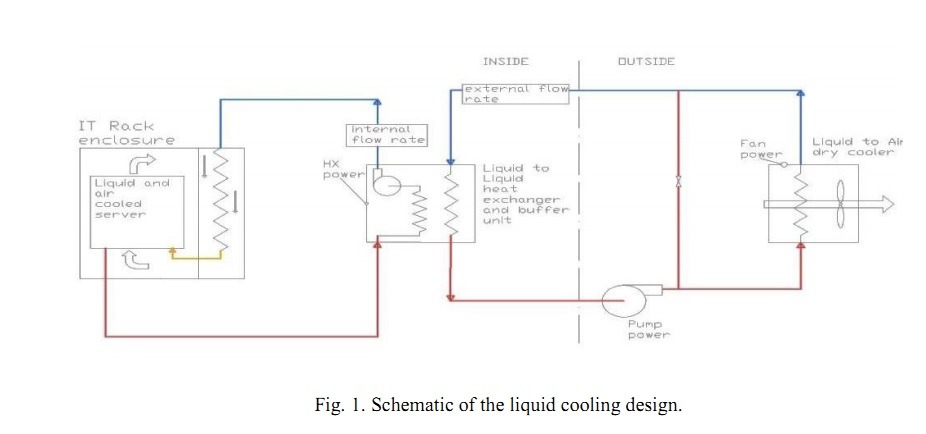
In [5,23] several experimental tests were conducted on the IBM chiller-less data center test facility, with a 15 kW fully populated rack, where server-level cooling was achieved through a combination of liquid cooling and re-circulation air. The cabinet was designed to house an air-to-liquid heat exchanger to cool the exhaust air from the servers. The coolant enters in the cabinet flowing through the air-to-liquid heat exchanger, and then flows through
the servers completing the cooling process. The servers were designed to accept inlet coolant temperature as high as 45 °C. Then hot water flow through a liquid-to-liquid heat exchanger, where the heat is transferred to the external loop. The separation between internal and external loop allows the use of water for the internal loop even during the winter months, using a glycol mixture for the external loop. From the heat exchanger the coolant flows to the dry cooler, where the heat is rejected. In this facility, unlike common data center, the cooling system have only three powered cooling devices constituted by the external dry cooler fans, the external pump and the internal pump. A 22 hours test in a relatively hot summer day was conducted on this facility. As a result, the cooling consumption was only the 3.5% [5, 23] of the rack power absorption, with an average IT load of 13.16 kW and an average cooling
power of 0.442 kW during the test. Since the test was conducted in a hot summer day, the average cooling power for a full year could be expected to be below 3.5 %. Fig. 1 shows a schematic representation of the cooling design.
In Zimmermann et al. [20] the energy performance of Aquasar, the first hot water cooled supercomputer prototype was analyzed. On the server level, the liquid cooling was achieved with cold-plate heat exchangers placed on every component dissipating more than 3 W, connected to the liquid loop, as shown in figure 2.a. The prototype consists also of an air cooled system in order to carry out a direct comparison of performance between the two
cooling solutions. The cooling system has three cycles, with building heating grid as final loop, where the waste heat was reused. An intermediate loop was necessary to prevent overheating of the system. The air cooled system uses air with an inlet temperature of 23°C, while in the liquid the cooling water is supplied with a temperature between 30°C and 60°C. It was demonstrated that the temperature difference between the electronics and coolant was over 35°C for the air cooling system while only 15°C for liquid cooling. These figures allowed to reuse up to 80% of the recovered heat in a building heating grid, when the inlet temperature was 60°C. Moreover, the calculated PUE was 1.15.
Another emergent liquid cooling technology is the fully immersed direct liquid-cooled system, as proposed in [15, 24]. The server enclosure is sealed and contains a fluoro-organic dielectric coolant in direct contact with electronics, which is used to transfer heat to a water jacket by natural convection. The heat can be then directly transferred from the cabinet to an external loop and eventually released or reused. In [18], Chi et al. made a
performance comparison between an air-cooled system and a fully immersed liquid-cooled system. Data were acquired from two operational systems of the University of Leeds, namely the 250 kW data center and a fully immersed liquid-cooled cabinet. In order to compare the two different cooling technologies, two hypothetical systems with identical IT hardware were built. The air-cooled system used an active rear door heat exchanger connected to a large scale chiller, while the liquid-cooled system used a dry cooler to directly discharge to the environment the heat collected by the water loop. The results show that the liquid-cooled system allows about 96 kW of power savings and 88% of cooling energy saving compared to the air-cooled system. Furthermore, the liquid-cooled allowed to achieve a PUE of 1.14, while the air-cooled a PUE of 1.48. In literature a wide range of operation temperatures for liquid-cooled systems can be found. For instance, in [25] inlet temperatures in the order of 45-70°C are adequate for maintaining the IT equipment below the temperature limits. According to [20], the inlet temperatures can range between 30°C and 60°C. The solution presented in [21] has an inlet temperature between 15°C and 45°C, whereas the case study presented in [18] has an inlet temperature of 50°C. In table 3 typical operating temperatures for a fully immersed liquid-cooled system are shown. Another advantage is the considerable fan energy saving and a lower noise level. On the other hand, the main drawback of liquid-cooled systems is the introduction of liquid within the data center and the potential damage that a failure can cause.
In table 4 a summary of the air and liquid cooling system characteristics is provided.2.3. Economizer modes
The use of the cooling system in economizer mode, generally called free cooling, is one of the most effective solution to obtain energy saving [26]. It allows the use of outside favorable climate conditions for the cooling process through the by-pass or partial load work of the mechanical active component resulting in energy and cost savings. The geographical position of the data center in an economizer mode perspective acquires large importance and can be considered an efficiency parameter.
There are two free cooling categories, air-side free cooling and water-side free cooling. The air-side free cooling can be direct or indirect and acts directly on the air within the data center. Direct free-cooling can be achieved blowing outside cold air directly into the data center when outside conditions fulfill specific conditions. Despite the simplicity and effectiveness, direct air-side free cooling can introduce in indoor environment humidity, particulates
and gaseous contaminants affecting the IT reliability. On the contrary indirect air-side free cooling avoids contamination by using an air-to-air heat exchanger. In some cases an evaporative cooling process is used to increase the temperature difference between the two air streams. Water-side free cooling act on the main heat transfer fluid, using an alternative path to by-pass the active component. In [27] Cho et al. analyzed, through an
energy simulation, the energy performance of air-side and a water-side economizers on a business data center located in Korea (temperate and subtropical climate). The two different economizer solutions were compared with a reference base cooling system, a chilled water system. The simulation was based on Seoul climate data. The results of the simulation showed that the air-side economizer worked for 57% of the total data center operation period, while the water-side economizer for about 35%. These numbers led to an annual energy savings of 16.6% and 42.2%, respectively for the water-side and the air-side economizer cooling system, compared with the base cooling system. The calculated PUE was 1.62 for the air-side economizer system and 1.81 for the water-side economizer system (the PUE estimated for the base cooling system was 1.92). In [7] Lee et al. performed an energy simulation to study the potential energy savings of the air-side economizers technology for 17 different climate zones. The simulation was carried out considering indoor conditions suggested by ASHRAE guidelines. Results showed that for very dry or humid climate zones the benefits of free cooling are overcome by humidification/dehumidification and fan energy costs necessary to maintain air within the recommended environmental limits.
As stated in [26], direct air-side economizer is adopted in the 40% of the total number of data centers using free cooling technologies. Moreover, both Yahoo and Facebook provide their facilities with advanced air-side economizer based cooling system, avoiding the use of chillers. These facilities are capable of operating 99% of time in economizer mode. As presented in [28] the design of a cost-effective data center taking advantage of outside air
eliminates the need of mechanical equipment. The data center exploits also the shape of the building, which was designed emulating a chicken-coop building, in order to take advantage of natural convection in the heat rejection.
Cool air enters from the side of the building, and, after cooling the equipment, exhaust air rises through a cupola in the roof. The system uses a direct air-side economizer for the heat removal, with an evaporative cooling assistance for extreme summer conditions. The achieved PUE is 1.08. Another example of extreme efficiency data center design it is given by the Open Compute Project (OCP), started by Facebook with aim to build the most efficient data center. Every aspect of the data center was completely re-designed and a new standard was created. Dedicated server, racks, power distribution, UPS and cooling system were developed, with the purpose to achieve the greatest operational cost savings. The built-up cooling system [29] of the open compute data center exploits outside air in direct free cooling with evaporative cooling assistance when needed, avoiding the need of mechanical equipment such chillers. The OCP server and racks were developed to accept higher inlet air temperature, beyond the ASHRAE guidelines. The declared Prineville OCP data center PUE is 1.06. Nevertheless, achieve such efficiency and PUE level in smaller data center or multi-tenants data center is very difficult.2.4. Future cooling strategies
Future DC applications will have higher number of transistor for chip and clock rates following Moore’s law, which in turn would lead to a further increase in heat dissipation density. To balance this high heat density several cooling technologies are being developed, such as fully immersed direct liquid-cooled, micro-channel single-phase flow or micro-channel two-phase flow. The cooling technology with the higher heat removal capacity is by far
micro-channel two-phase flow system, which takes advantage of the latent heat of the fluid. The use of the latent heat leads to a greatly increased convection heat transfer coefficient due to nucleate boiling compared to the sensible heat of a single-phase fluid. As stated in [2], two-phase cooling could remove higher heat fluxes while working with smaller mass flow-rates and lower pumping power than a single-phase cooling solution. Moreover, if properly designed [3], two-phase cooling could provide a more uniform equipment temperature. Coolant temperature can reach 80°C increasing the quality of the heat and allowing an easy reuse in several applications. As demonstrated by Ohadi et al. [19] with a CFD simulation, a flow rate of 0.54 g/s with an entering temperature of 76.5°C can be sufficient to cool an 85 W CPU. In [3] Marcinichen et al. proposed and simulated a two-phase cooling cycle and the relative energy performance as well as energy recovery opportunities. Five cases scenario were simulated with three different coolants. Results showed that the liquid single-phase cycle had a pumping power consumption 5.5 times higher than the HFC134a two-phase cooling cycle.2.5. Waste Heat Recovery
A further step for improving energy efficiency and reducing energy consumption in data center is the capture and reuse of the waste heat produced by the IT equipment. The implementation of waste heat recovery measures can have a great effect on reducing CO2 emissions. Nevertheless the main impediment to introduce a WHRU (Waste Heat Recovery Unit) in a data center is the low quality of the heat produced, despite the large quantity. In fact the heat production is bound by the maximum electronics temperature, which in most case remains below 85°C.
Different cooling technologies offer various options of WHRU implementation. Air-cooled systems for example have temperature limitations that allow an effective reuse only for building heating or hot-water production systems.
In fact in such systems the waste heat temperature ranges between 30-45°C. Liquid and two-phase cooled systems on the other hand have higher operational temperature, closer to the electronics limit temperature. High temperatures as 60-70°C for liquid-cooled systems and 70-80°C for two-phase cooling systems [3] provide higher waste heat quality and open up a wide range of waste heat reuse opportunities. In [2], Ebrahimi et al. analyzed several waste heat recovery technologies that could be applied to data centers. Building or district heating, absorption cooling, Rankine Cycle, Organic Rankine Cycle (ORC), biomass co-location, and desalination for clean water production are options for reusing waste heat in data center. The reuse of the heat in building heating systems is relatively common in data centers due to simplicity and lower heat quality requirement. Most technologies are not compatible with air-cooled systems or need thermal boost as opposed to liquid and two-phase cooled system. Most of the waste heat recovery options require co-located siting, making the retrofit into existing data center impossible. It was found that absorption cooling and organic Rankine cycle were the most promising and economically beneficial technologies for data center waste heat reuse. In fact absorption cooling offers an extra source of chilled water for additional cooling, that results in a cooling requirement reduction, while ORC provide on-site electricity generation that can reduce the electricity requirement.2.6. Renewable energy sources and Thermal energy storage integration into data centers
Another step toward the reduction of CO2 emissions in data center industry is the implementation of renewable energy sources (RES) to cover part of data centers overall energy consumption. The main obstacle is the intermittent nature of RES, whereas data center require energy 24h per day every day, which needs to be provided even when green power is not available. Some examples of RES implementation in data center are the 100 kW solar panel array on the data center roof on Emerson’s campus in Missouri [30] or the 1.7 MW solar panel array of Google HQ in Mountain View. Other options available are the off-site generation or the purchase of renewable energy generated by others, such in the case of a Power Purchase Agreement (PPA). An example is the PPA contracted by Google to buy 114 MW of wind power [30]. Thermal energy storage (TES) integration in data center is another solution to reduce energy consumption, especially for obtaining peak electrical demand savings. A TES system can store cold from the environment when the conditions are favorable and releases it when necessary. As stated in [30], the cooling system energy consumption of a 300 kW data center can be reduced by 20% with a TES system using water as storage material. Moreover, TES systems improve cooling system reliability. As pointed out in [31], in chilled water systems a water TES system can be used also during utility power outage events to provide the cooling capacity until the chiller is restarted.
3. Conclusions
In this paper an analysis on several currently available and emerging data center cooling systems was carried out. The advantages and drawbacks of different technologies were discussed. A variety of aspects that needs to be carefully examined such as waste heat recovery, RES and TES integration into data center was discussed. Improve energy efficiency is crucial, not only to allow a supportable industry growth but also to reduce operational costs.
Energy efficiency measures comprise aisles containment, higher supply air temperature, optimal air distribution and free cooling exploitation. Another option to efficiently address the cooling process is the adoption of liquid cooling solutions, that are capable of supporting high density power and offer a wide range of advantages. In order to further increase energy savings, the evolution of cooling systems is going towards the elimination of active mechanical equipment. Both liquid cooling and advanced air-side economizer based cooling systems can potentially allow the reduction of using mechanical equipment and the achievement of higher efficiency levels.References
[1] Koomey J. Growth in data center electricity use 2005 to 2010. A report by Analytical Press, completed at the request of The New York
Times. 2011.
[2] Ebrahimi K, Jones GF, Fleischer AS. A review of data center cooling technology, operating conditions and the corresponding low-grade
waste heat recovery opportunities. Renew Sust Energy Rev 2014;31:622–38.
[3] Marcinichen JB, Olivier JA, Thome JR. On-chip two-phase cooling of datacenters: Cooling system and energy recovery evaluation. Appl
Therm Eng 2012; 41: 36-51
[4] Anandan SS, Ramalingam V. Thermal management of electronics: A review of literature. Therm Sci 2008; 12(2): 5-26.
[5] Iyengar M, David M, Parida P, Kamath V, Kochuparambil B, Graybill D, Schultz M, Gaynes M, Simons R, Schmidt R, Chainer T. Server
liquid cooling with chiller-less data center design to enable energy savings. In: Proceedings of the 28th IEEE SEMI-THERMsymposium. San
Jose (CA, USA); 18–22 March, 2012. p. 212–23.
[6] ASHRAE whitepaper. Thermal guidelines for data processing environments— expanded data center classes and usage guidance, Technical
Committee (TC) 9.9, ASHRAE; 2011.
[7] Lee KP, Chen HL. Analysis of energy saving potential of air-side free cooling for data centers in worldwide climate zones. Energ Buildings
2013; 64: 103-112.
[8]Bellia L.; Capozzoli A.; Mazzei P.; Minichiello F., A comparison of HVAC systems for artwork conservation, International Journal of
Refrigeration, p. 1439-1451, 2007, Vol. 30, Issue 8.
[9] Evans T. The different technologies for cooling data centers. APC white paper 2012; 59.
[10] Schmidt RR, Cruz EE, Iyengar MK. Challenges of data center thermal management. IBM J Res Dev 2005;49(4/5):709–23
[11]Capozzoli A, Chinnici M, Perino M, Serale G. Review on Performance Metrics for Energy Efficiency in Data Center: The Role of Thermal
Management, LECT NOTES COMPUT SC, Vol. 8945, 2015, pp 135-151.
[12] Capozzoli A, Serale G, Liuzzo L, Chinnici, M. Thermal Metrics for Data Centers: A Critical Review. Energy Procedia, 2014; 62, 391-400.
[13] Cho J, Yang J, Park W. Evaluation of air distribution system’s airflow performance for cooling energy savings in high-density data centers.
Energ Buildings 2014; 68: 270–279.
[14] Lu T, Lü X, Remes M., Viljanen M. Investigation of Air Management and Energy Performance in a Data Center in Finland: Case study.
Energ Buildings 2011; 43(12): 3360– 3372.
[15] Niemann J, Brown K, Avelar V. Impact of Hot and Cold Aisle Containment on Data Center Temperature and Efficiency. APC White Paper
2011; 135.
[16] Dunlap K, Rasmussen N. Choosing Between Room, Row, and Rack-based Cooling for Data Centers. APC White Paper 2012; 130.
[17] Almoli A, Thompsion A, Kapur N, Summers J, Thompson H, Hannah G. Computational fluid dynamic investigation of liquid rack cooling
in data centres. Appl Energ 2012;89:150–5.
[18] Chi YQ, Summers J, Hopton P, Deakin K, Real A, Kapur N, Thompson H. Case Study of a Data Centre Using Enclosed, Immersed, Direct
Liquid-cooled Servers. In: Proceedings of the 30th IEEE SEMI-THERM symposium. San Jose (CA, USA); March 9-13, 2014. p. 164-173.
[19] Ohadi MM, Dessiatoun SV, Choo K, Pecht M, Lawler JV. A comparison analysis of air, liquid, and two-phase cooling of data centers. In:
Proceedings of the 28th IEEE SEMI-THERM symposium. San Jose (CA, USA); March 18–22, 2012. p. 58–63.
[20] Zimmermann S, Meijer I, Tiwari MK, Paredes S, Michel B, Poulikakos D. Aquasar: A hot water cooled data center with direct energy reuse.
Energy 2012; 43(1): 237-245.
[21] Coles H. Direct Liquid Cooling for Electronic Equipment. 2014.
[22] ; 2015 [accessed March 2015]
[23 ] Iyengar M., David M, Parida P, Kamath V, Kochuparambil B, Graybill D, Schultz M, Gaynes M, Simons R, Schmidt R, Chainer T.
Extreme energy efficiency using water cooled servers inside a chiller-less data center. In Thermal and Thermomechanical Phenomena in
Electronic Systems (ITherm), 2012 13th IEEE Intersociety Conference on (pp. 137-149). IEEE.
[24] ; 2015 [accessed March 2015]
[25] Kim M, Ham S, Park J, Jeong J. Impact of integrated hot water cooling and desiccant-assisted evaporative cooling systems on energy
savings in a data center. Energy 2014; 78: 384-396.
[26] Zhang H, Shao S, Xu H, Zou H, Tian C. Free cooling of data centers: A review. Renew Sust Energ Rev 2014; 35: 171-182.
[27] Cho J, Lim T, Kim BS. Viability of data center cooling systems for energy efficiency in temperate or subtropical regions: Case study. Energ
Buildings 2012; 55: 189-197.
[28] Robison A D, Page C, Lytle B. Yahoo! Compute Coop (YCC): A Next-Generation Passive Cooling Design for Data Centers. No.
DOE Yahoo! Inc., Sunnyvale, CA, 2011.
[29] J. Park. Open Compute Project-Data Center v1.0. Facebook, Inc., Menlo Park, CA, USA [Online]. 2011. Available:[30] Orón E, Depoorter V, Garcia A, Salom J. Energy efficiency and renewable energy integration in data centres. Strategies and modelling
review. Renew Sust Energ Rev 2015;42:429–445
[31] Lin M, Shao S, Zhang X, Vangilder JW, Avelar V, Hu X. Strategies for data center temperature control during a cooling system outage.
Energ Buildings 2014; 73: 146-152.Original Link:
Attachments: