
Single-Phase Transformer
Single-phase transformer may be connected to obtain three-phase power. These are found at many Reclamation facilities, at shops, offices, and warehouses.
ANSI standard connections are illustrated below in the following figures. There are other angular displacements that will work, but are seldom used. Do not attempt to connect single-phase units together in any combination that does keep the exact angular displacement on both primary and secondary; a dangerous short circuit could be the result. Additive and subtractive polarities can be mixed (see the following figures).
These banks also may be paralleled for additional capacity if the rules are followed for three-phase paralleling. When paralleling individual three-phase units or single-phase banks to operate three-phase, angular displacements must be the same.
Figure 1 shows delta-delta connections. Figure 2 shows wye-wye connections, which are seldom used at Reclamation facilities, due to inherent third harmonic problems. Methods of dealing with the third harmonic problem by grounding are listed below. However, it is easier just to use another connection scheme, to avoid this problem altogether. In addition, these schemes are much more familiar to Reclamation personnel.
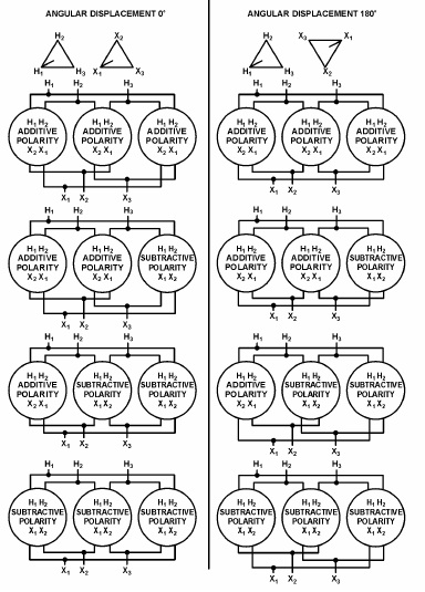
Figure 1 – Delta-Delta Connections, Single-Phase Transformers for
Three-Phase Operation
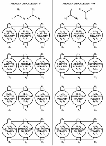
Figure 2 – Wye-Wye Connections, Using Single-Phase Transformers
for Three-Phase Operation
Single-Phase Transformer Paralleling
In perfect parallel operation of two or more transformers, current in each transformer would be directly proportional to the transformer capacity, and the arithmetic sum would equal one-half the total current. In practice, this is seldom achieved because of small variations in transformers. However, there are conditions for operating transformers in parallel. They are:
1. Any combination of positive and negative polarity transformers can be used. However, in all cases, numerical notations must be followed on both primary and secondary connections. That is H1 connected to H1, H2 connected to H2, and X1 connected to X1, X2 connected to X2, X3 connected to X3. Note that each subscript number on a transformer must be connected to the same subscript number on the other transformer as shown in figure
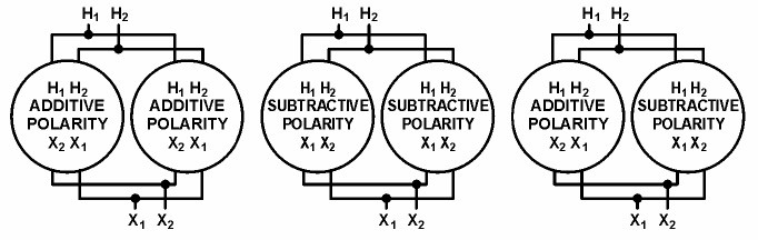
With positive and negative polarity transformers, the location of X1 and X2 connections on the tanks will be reversed. You must take care to ensure that terminals are connected, as stated above.
2. Tap settings must be identical.
3. Voltage ratings must be identical; this, of course, makes the turns ratios also identical.
4. The percent impedance of one transformer must be between 92½% and 107½% of the other. Otherwise, circulating currents between the two transformers would be excessive.
5. Frequencies must be identical. Standard frequency in the United States is 60 hertz and usually will not present a problem.
One will notice, from the above requirements, that paralleled transformers do not have to be the same size. However, to meet the percent impedance requirement, they must be nearly the same size. Most utilities will not parallel transformers if they are more than one standard kVA size rating different from each other; otherwise, circulating currents are excessive.
 CMM-12R Oil Regeneration ...