Three-Phase Transformer
There are main different types of oil transformers, that we can discuss. Figures below show principles of single-phase and three-phase transformer. We can also look at special technological devises and methods, that can optimize and improve oil transformers.
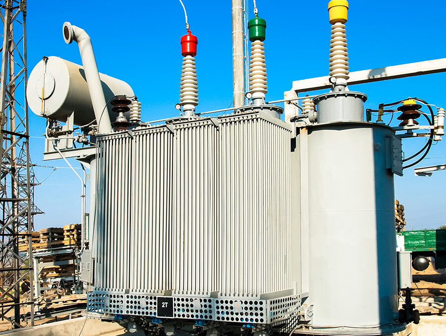
Three-phase power is attainable with one three-phase transformer, which is constructed with three single-phase units enclosed in the same tank or three separate single-phase transformers. The methods of connecting windings are the same, whether using the one three – phase transformer or three separate single-phase transformers.
Potential transformers are usually rated 50 to 200 volt-amperes at 120 secondary volts. The secondary terminals should never be short circuited because a heavy current will result, which can damage the windings.
Oil Transformers connections
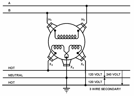
To provide flexibility for connection, the secondary winding is arranged in two sections. Each section has the same number of turns and, consequently, the same voltage.
Two primary leads (H1, H2) are brought out from the top through porcelain bushings. Three secondary leads (X1, X2, X3) are brought out through insulating bushings on the side of the tank, one lead from the center tap (neutral) (X2) and one from each end of the secondary coil (X1 and X3). Connections, as shown, are typical of services to homes and small businesses. This connection provides a three-wire service that permits adequate capacity at minimum cost.
The neutral wire (X2) (center tap) is grounded. A 120-volt circuit is between the neutral and each of the other leads, and a 240-volt circuit is between the two ungrounded leads.
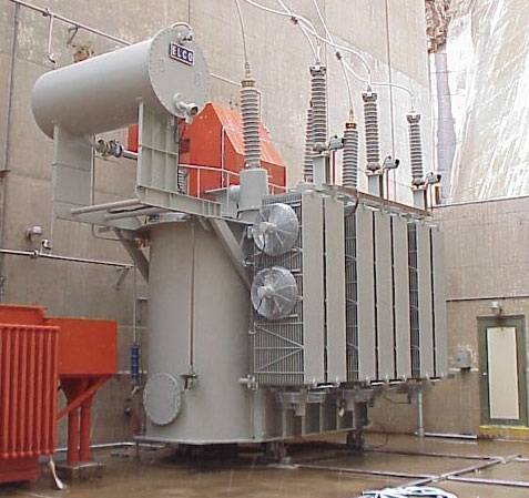
Typical GSU Three-Phase Transformer
Pole-top and small, pad-mounted transformers that serve residences and small businesses are typically distribution transformers. Generator step-up transformers, used in Reclamation powerplants, receive electrical energy at generator voltage and increase it to a higher voltage for transmission lines. Conversely, a step-down transformer receives energy at a higher voltage and delivers it at a lower voltage for distribution to various loads.
All electrical devices using coils (in this case, transformers) are constant wattage devices. This means voltage multiplied by current must remain constant; therefore, when voltage is “stepped-up,” the current is “stepped-down” (and vice versa).
Three-Phase Transformers transfer electrical energy between circuits completely insulated from each other. This makes it possible to use very high (stepped-up) voltages for transmission lines, resulting in a lower (stepped-down) current. Higher voltage and lower current reduce the required size and cost of transmission lines and reduce transmission losses as well. Transformers have made possible economic delivery of electric power over long distances. Transformers do not require as much attention as most other equipment; however, the care and maintenance they do require is absolutely critical. Because of their reliability, maintenance is sometimes ignored, causing reduced service life and, at times, outright failure.
The large horizontal tank at the top three-phase transformer is a conservator. Transformers are typically used because a change in voltage is needed. Power transformers are defined as transformers rated 500 kVA and larger. Larger transformers are oil-filled for insulation and cooling; a typical GSU transformer may contain several thousand gallons of oil. One must always be aware of the possibility of spills, leaks, fires, and environmental risks this oil poses.
Transformers smaller than 500 kVA are generally called distribution transformers.
 Mojave Heat (Sukhovey): ...
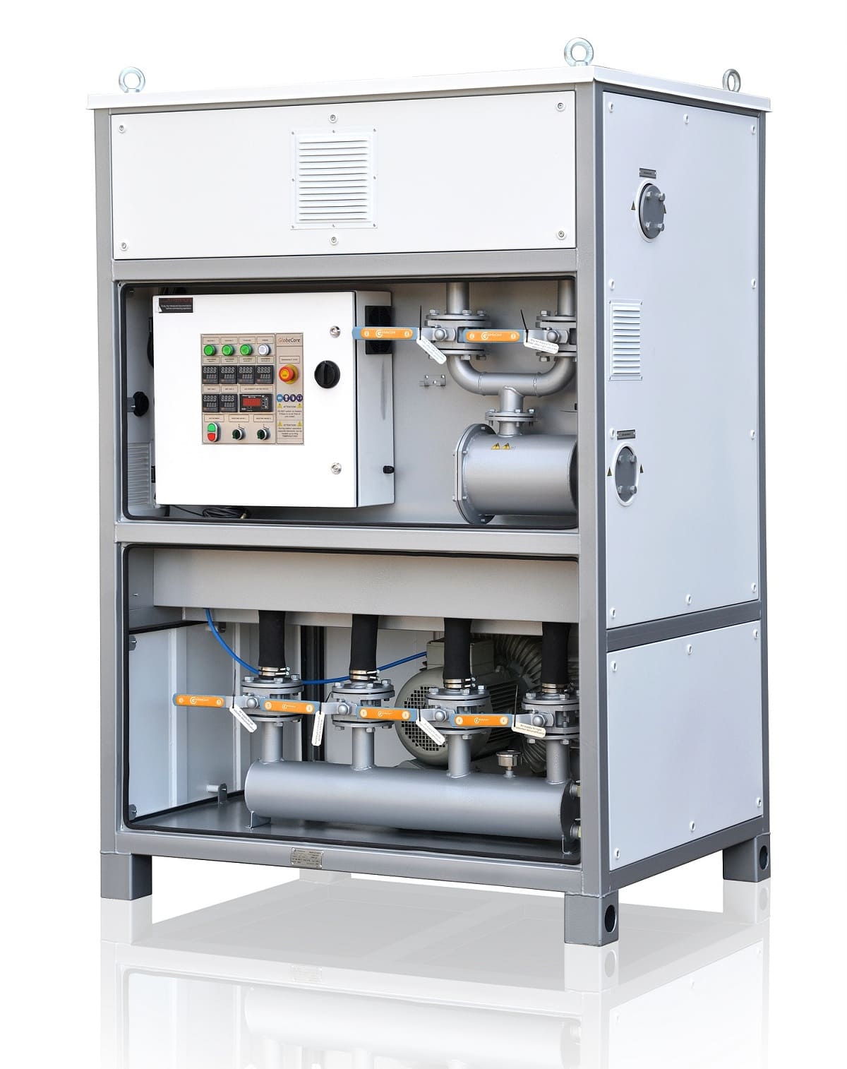
 PPM Inline Oil ...
 CMM-4/7 portable oil ...