PT-PT
PT-PT
 FR
FR
 ES
ES
 DE
DE
 AR
AR
 PL
PL
 UA
UA
 ID
ID
 VN
VN
 IT
IT
 GE
GE
 UZ
UZ
 CN
CN
 KZ
KZ
 CZ
CZ


In this article, we will discuss drilling mud production by means of a ferromagnetic particles vortex layer technology and evaluate the prospects of applying this technology in the oil and gas industry.
Drilling mud is an important part of the technology for development of mineral resources (oil and gas). It is responsible for several functions at once among which removing the disintegrated rock from the bottom hole, protecting the well against caving-in, doping the drill stem, etc. can be highlighted.
Drilling mud production is carried out using various formulations, but water-based and hydrocarbon-based muds are the most common. In the first case, the components such as service water, brines and hydrogels, polymer, polymer-clay, and clay solutions are used, and in the second case, inverted emulsions and lime-bitumen solutions are applied. Standard components cannot always ensure the necessary functions of drilling mud; therefore, in order to improve them, special modifiers adjusting the structural and rheological properties are used.
Drilling mud production normally takes place in special units the functioning of which is ensured due to the operation of various mixers, dispersers, etc.
Drilling mud production equipment
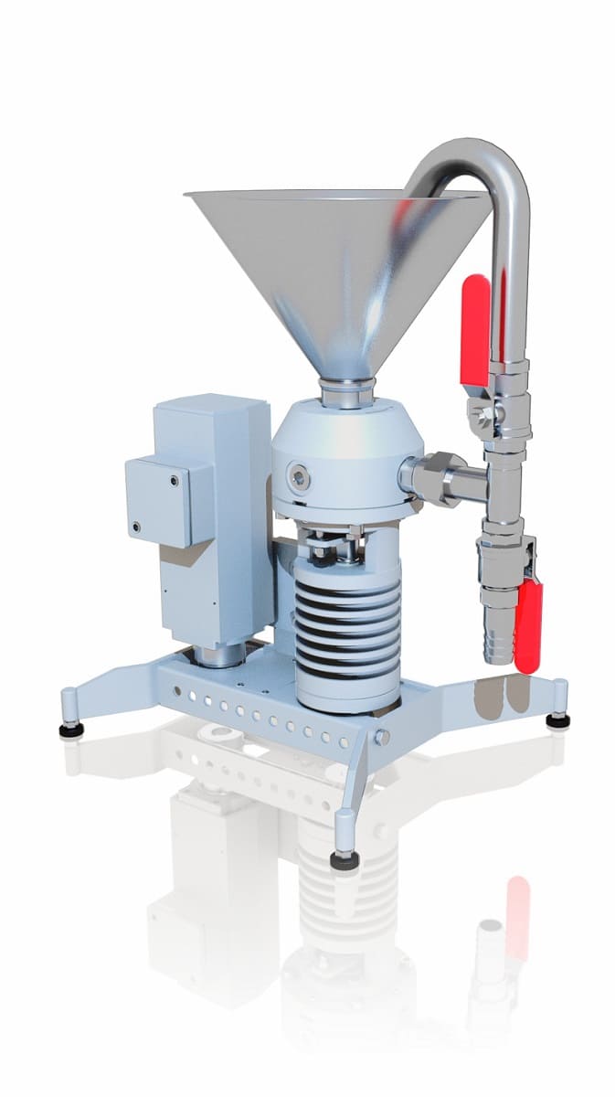
Let us discuss the main types of mixers and dispersers by means of which drilling mud is produced. In exploration drilling of oil and gas wells, under the conditions of autonomous deployment of rig sites, the hydraulic method is of great importance according to which only kinetic flow energy is used to disintegrate solid particles of clayey circulating fluids. A device that implements this principle of operation is called a hydraulic drilling mud mixer or a hydraulic agitator.
Centrifugal mixing is used at the final stage of drilling mud production. It is implemented by means of agitators in which clay particles are dispersed when exposed to rotation of paddles.
In terms of design, static (motionless) mixers constitute a special insert in the pipe through which the drilling mud slurry is supplied. These inserts can be of various lengths, diameters, and configurations which allows mixing the multicomponent materials of different chemical nature, viscosity, and density. The main task of a static drilling mud mixer is to homogenize the material, to condition the viscosity gradient, to prevent entrapped air from getting into the mixture, and to increase the flow turbulence.
In practice, the final mixing of components occurs only when the mud is run several times through all the mixers and dispersers in the production unit, i.e. several processing cycles take place. Considering the above, as well as the active participation of mechanical agitators in mixing, we can speak about a great amount of time and electricity spent on the drilling mud production process. Furthermore, it is not always possible to obtain the drilling mud of desired quality. Therefore, the development of new devices that will reduce the production time and the energy intensity of drilling muds while ensuring the proper quality characteristics is relevant and timely.
Drilling mud production by means of a vortex layer device
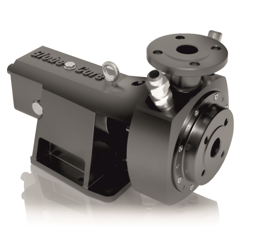
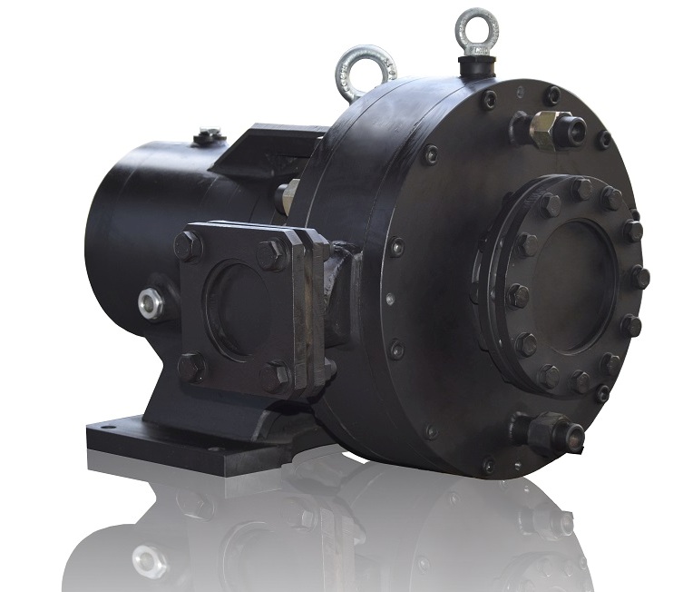
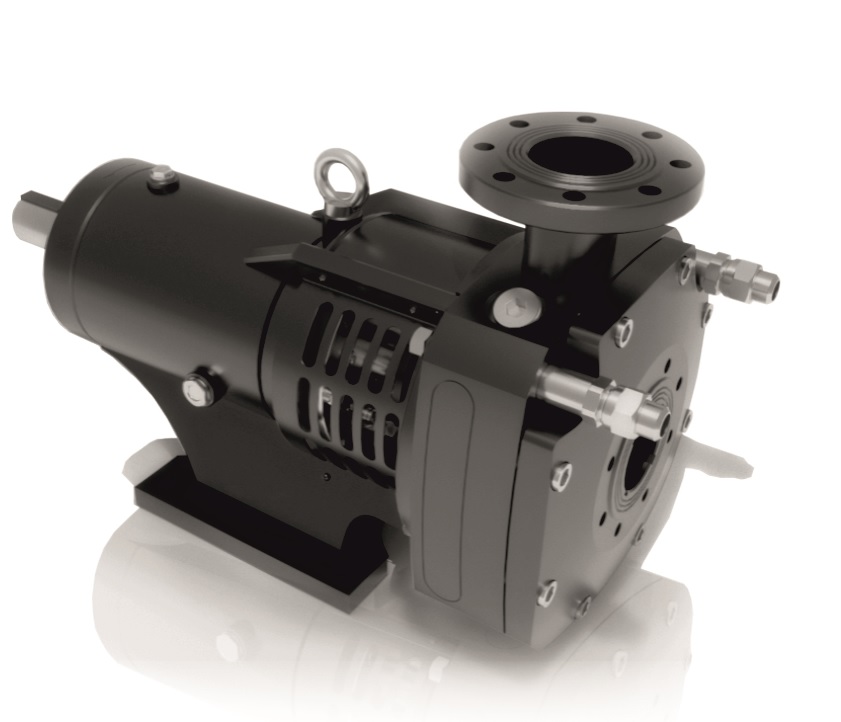
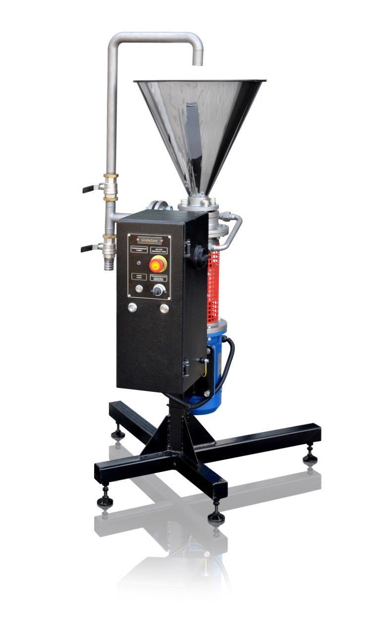
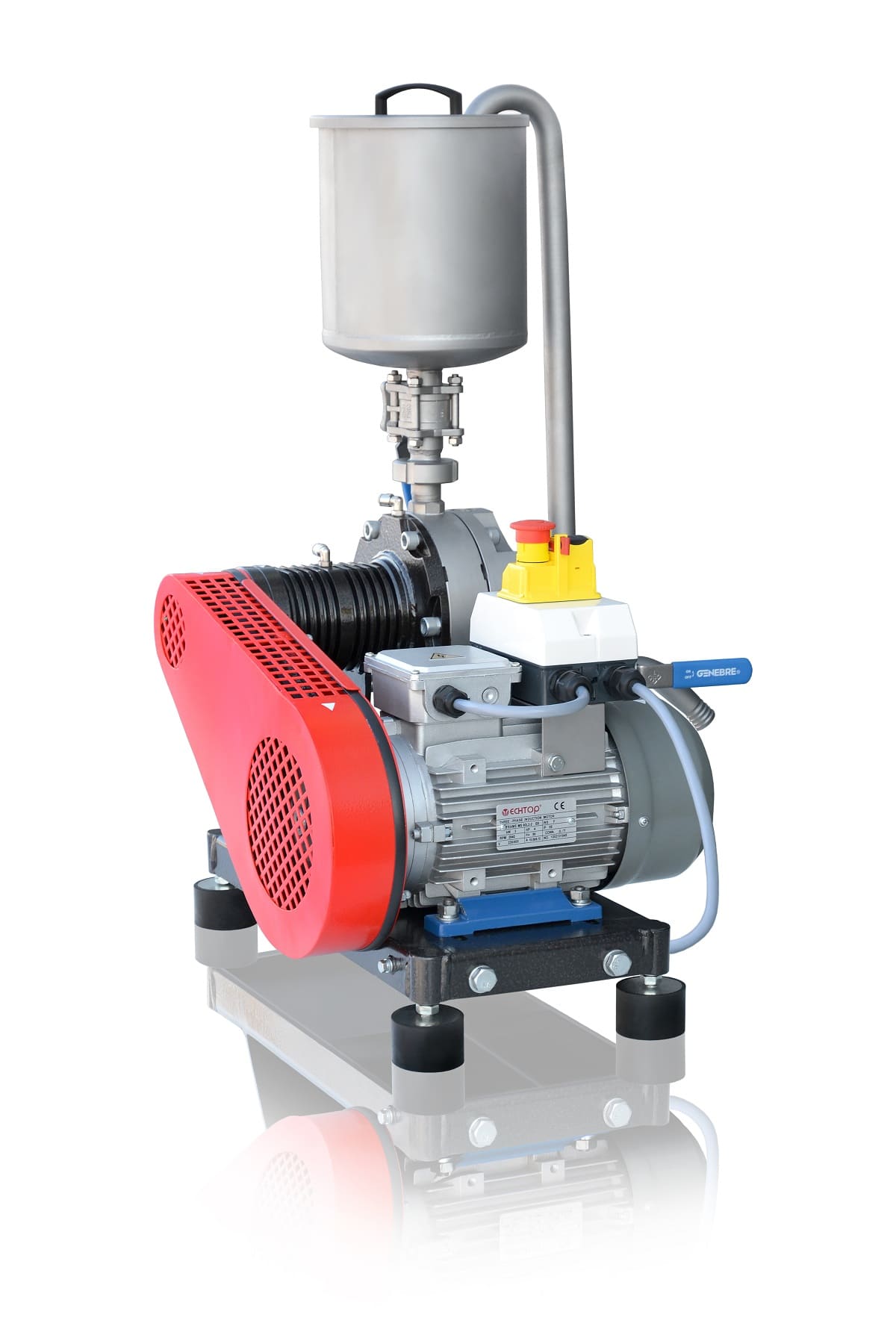
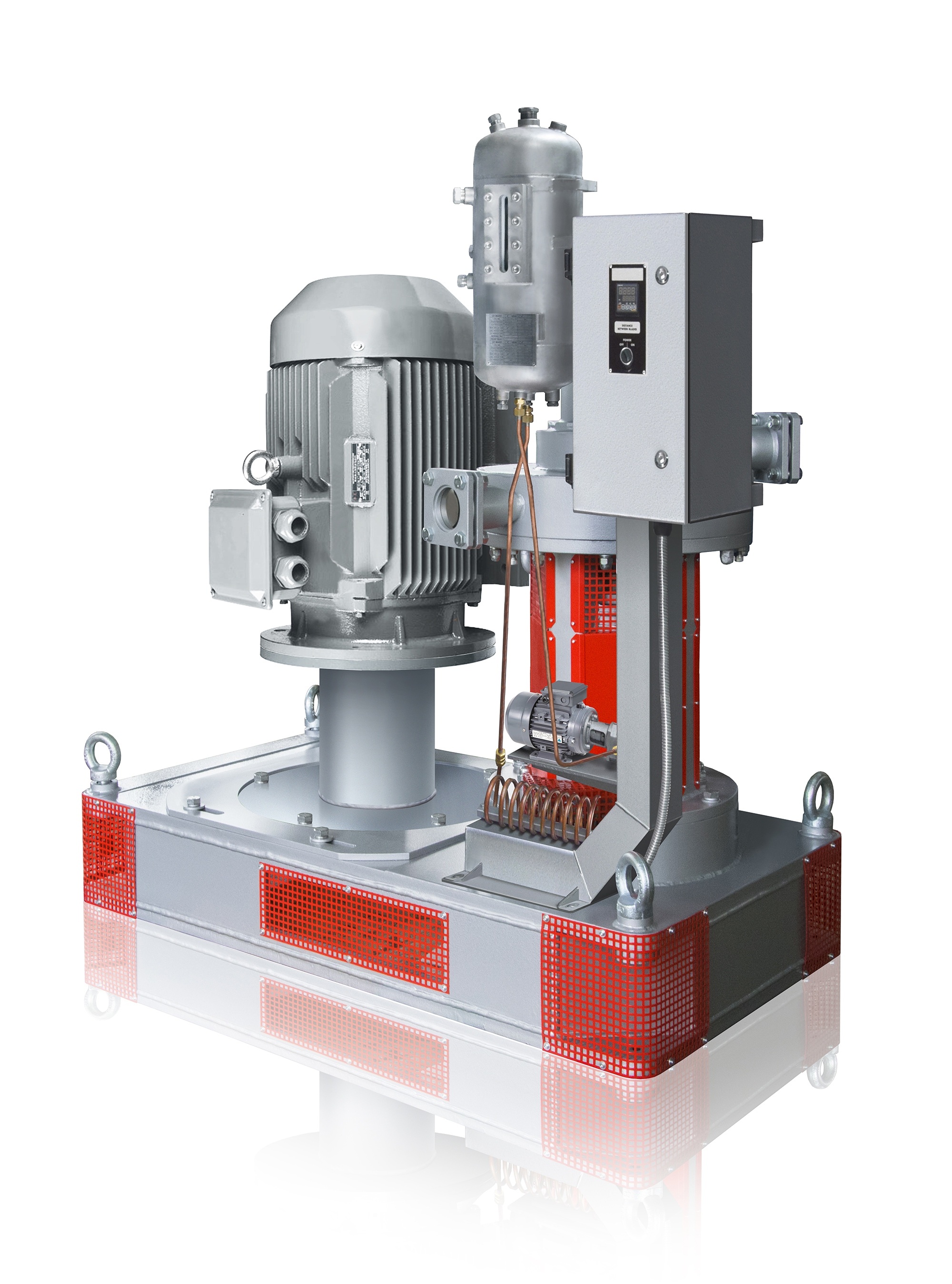
In terms of design, a vortex layer device constitutes an operating chamber placed into an inductor of rotating electromagnetic field (Figure 1).
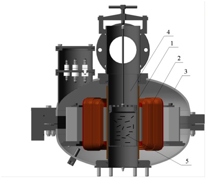
Figure 1. Device with a vortex layer of ferromagnetic particles: 1 – stainless steel (non-magnetic) bushing of operating chamber; 2 – inductor of rotating electromagnetic field; 3 – inductor housing; 4 – stainless steel (non-magnetic) operating chamber; 5 – ferromagnetic particles
Ferromagnetic particles are placed into the operating chamber — cylindrical elements with the diameter of 1 to 5 mm and the length of 1 to 50 mm (depending on the mixing technology) in the amount of several tens to several thousand pieces (0.05–5 kg) (the exact amount depends on the critical mass coefficient of particles in the device operating zone). The main feature of this device is the simultaneous course of various physical and chemical processes in the operating chamber.
Due to the geometric shape features of the inductor and the operating chamber, an electromagnetic field created by the inductor and the present magnetic induction of 0.11 to 0.15 T cause a so-called vortex layer where the vector direction of the radial component of element velocity is equally probable, and the tangential component is predominantly directed as the field moves which leads to a circular motion of the entire layer as a whole. In addition, the velocity component directed along the device axis influences the ferromagnetic particles when they collide with one another and with the chamber walls and when they are exposed to the flow of processed product. In this case, the particles move through the operating chamber. Each ferromagnetic element is a pronounced dipole magnet that begins to oscillate colliding with the rest of elements when it experiences reverse magnetism. The collision frequency dependence is directly proportional to the length to diameter ratio. The maximum value is observed at l/d=9….13. Among the most significant processes running in the device operating chamber and contributing to the active dispersion and mixing of substances, it is worth highlighting:
- electromagnetic field effect;
- mechanical effect of ferromagnetic particles on processed substance;
- hydrodynamic effect (high shear stresses in liquid, pressure and flow velocity fluctuations);
- hydroacoustic effect (intensive cavitation, shock waves);
- thermal effect;
- hydrolysis.
The energy of rotating electromagnetic field induces the internal energy of processed substance (surface layer activation). The power of the latter is very high.
The integrated effect of various phenomena in the device operating chamber due to which dispersion and mixing occur simultaneously, as well as a relatively small amount of energy spent on obtaining an electromagnetic field make it possible to suggest a hypothesis that drilling mud production by means of a vortex layer device will be more efficient. We carried out an experiment in order to test this hypothesis.
Results of experimental studies
For practical research, we applied the formulation of hydrocarbon-based drilling mud used to protect the well against caving-in. It consisted of diesel fuel (835 kg/m3), service water, emulsifier (20 L/m3), lime (20 kg/m3), organophilic clay (12 kg/m3), and halite (90 kg/m3).
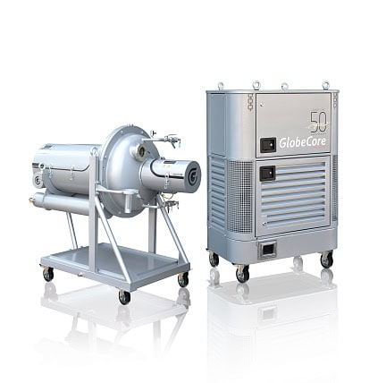
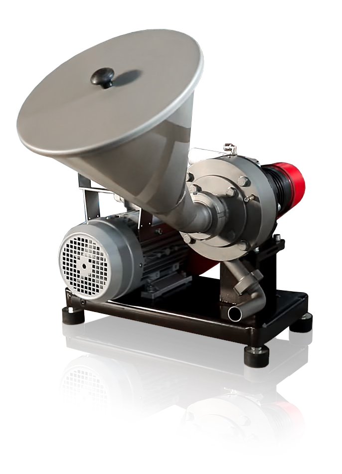
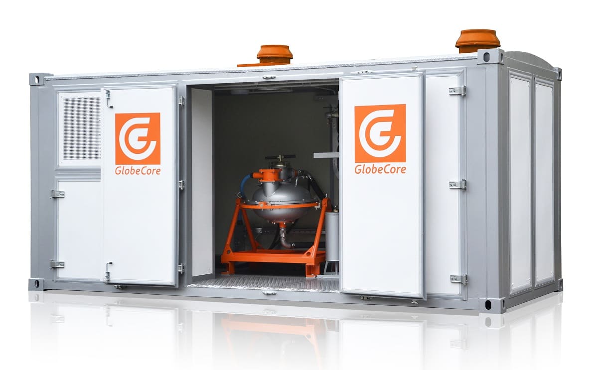
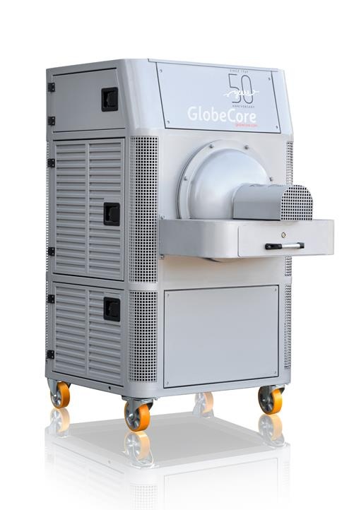
The efficiency of drilling mud production was studied using AVS-100 vortex layer device manufactured by GlobeCore and steel ferromagnetic elements with the diameter of 2 mm and the length of 20 mm. Ball-bearing wear-resistant steel was used to ensure the smallest grinding yield of metal in the processed drilling mud as a structural material of these elements.
|
|
|
|
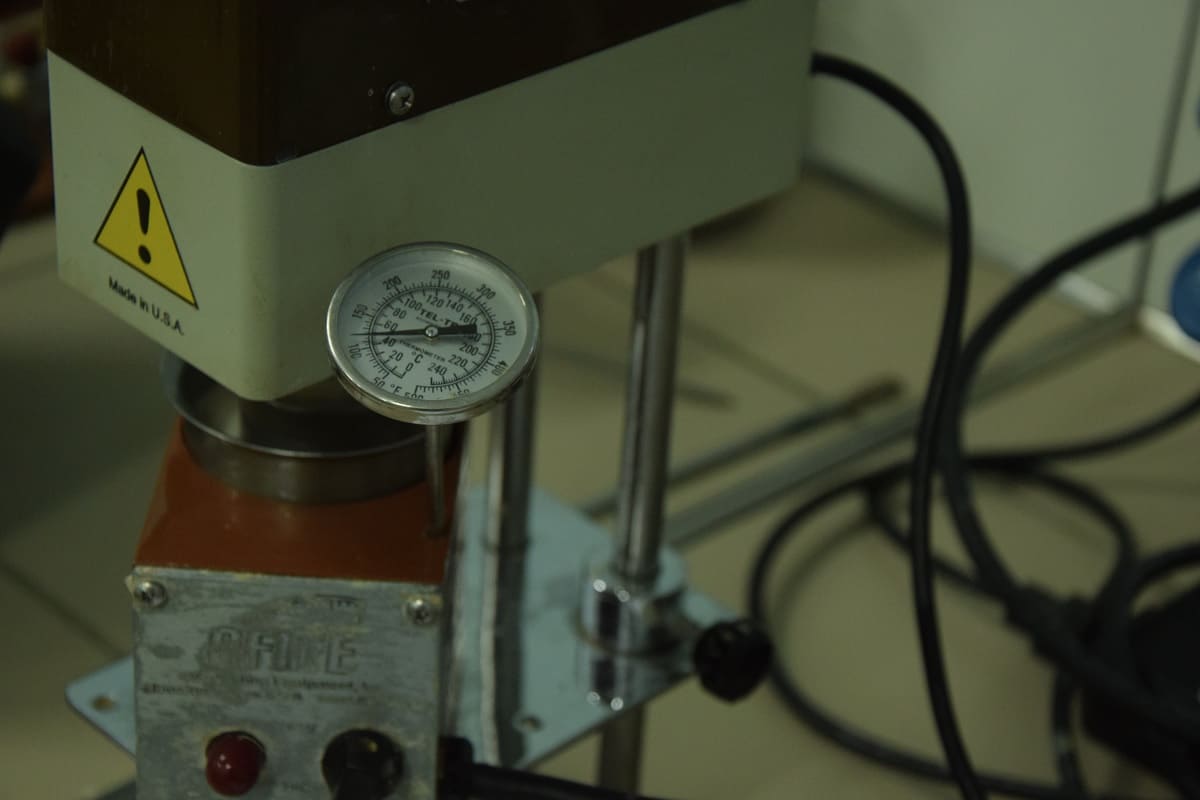
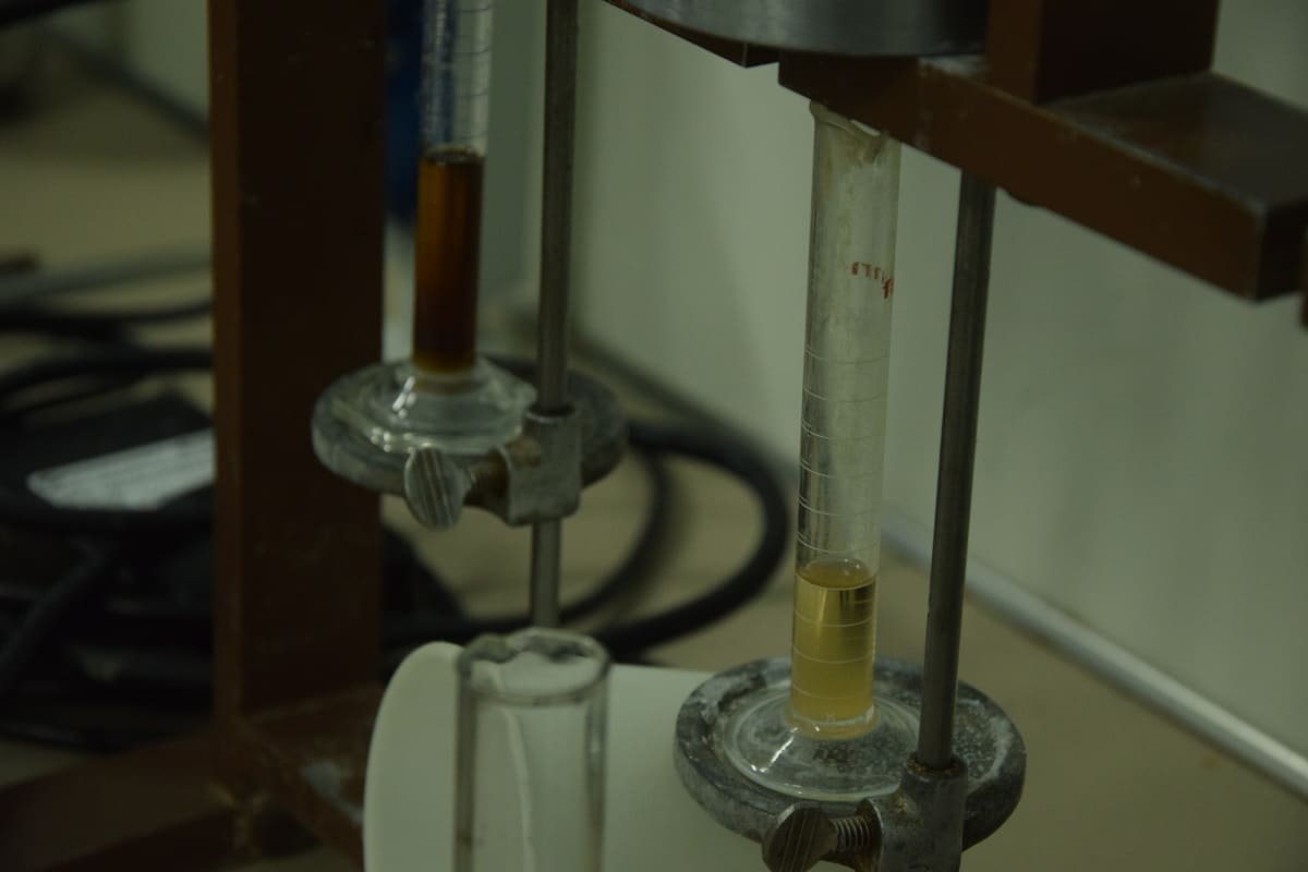
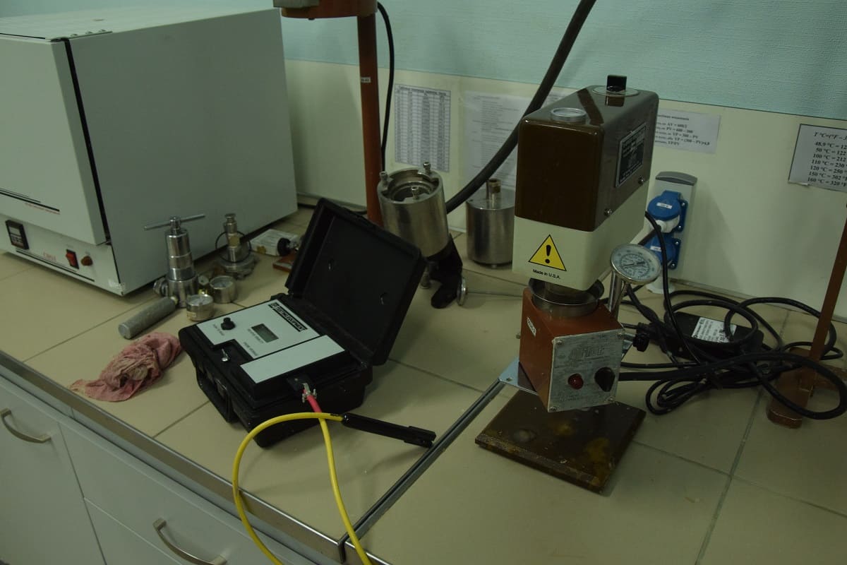
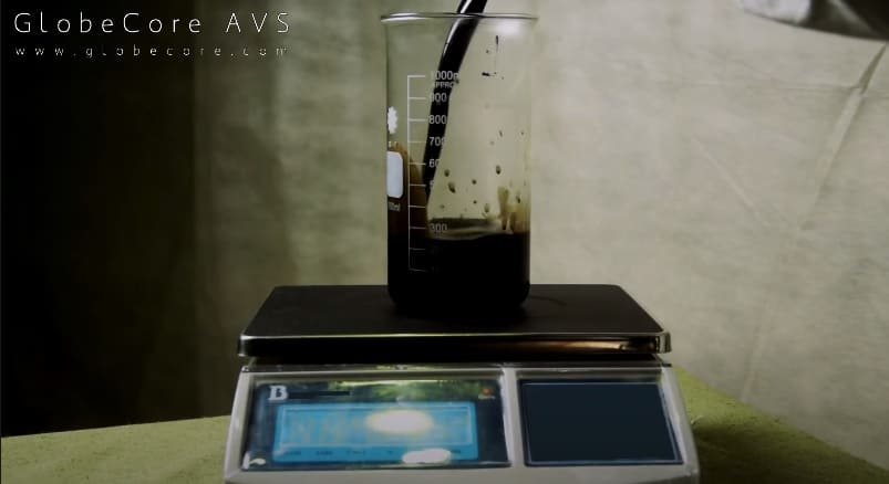
Figure 2 – Checking the plastic viscosity, filtration, and electrical stability of drilling mud
After obtaining the emulsion, the following parameters were checked: filtration, plastic viscosity, density, and electrical stability. The numerical values thereof are shown in Table 1.
Table 1 – Parameters of drilling mud obtained by means of AVS-100 vortex layer device
| No. | Parameter | Unit of Measurement | Numerical Value |
| 1 | Plastic viscosity | cP | 11 |
| 2 | Filtration | cm3 | 3.8 |
| 3 | Density | kg/m3 | 940 |
| 4 | Electrical stability | V | 429 |
The obtained data indicate a good quality of drilling mud for the production of which AVS-100 vortex layer device was used.
Conclusions based on the experiment results
The tests carried out allow drawing the following conclusions:
- Owing to various physical and chemical processes running in the operating chamber of the vortex layer device, it becomes possible to simultaneously disperse and mix the drilling mud by means of the same device. It allows simplifying the drilling mud production unit by removing other mixers and dispersers.
- The quality of the drilling mud obtained using a vortex layer device in one stage is not inferior to the quality of the drilling mud obtained in several processing cycles using mechanical agitators and dispersers.
- Replacing the mechanical agitators with a vortex layer device allows halving the electricity consumption required to obtain one cubic meter of drilling mud.
- Furthermore, using a vortex layer device, it was possible to reduce several times the time required for drilling mud production in comparison with the same indicator for the units equipped with mechanical agitators.
The capacity of AVS-100 device is 1–1.5 m3/h with the electricity input of 3.5–4 kW/h, and that of AVS-150 device is 2–2.5 m3/h with the electricity input of 9.5 kW/h.