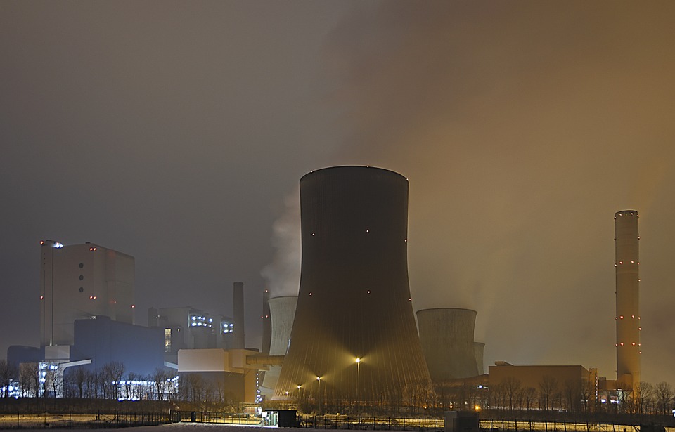
According to various estimates, the share of nuclear energy is at least 10–16% of all the energy resources generated in the world. In some countries, such as France, nuclear energy ranks high — 71.6%. In China, the share of nuclear energy does not exceed 4%. The use of nuclear energy is a matter of debate, because a range of real and possible problems is associated therewith:
- the need to dispose radioactive waste;
- accidents leading to environmental disasters (nuclear power plants in Chernobyl and Fukushima);
- nuclear power plants can be subject to terrorist attacks and are potential weapon of mass destruction;
- possible use of nuclear power plant fuel in nuclear weapon production.
But it is a fact of life that in spite of all hazards, nuclear energy cannot be completely replaced with other sources at this point and will be used by mankind in the near future. Therefore, at this stage, the task of reducing the hypothetical and real risks associated with operating the nuclear power plants remains relevant.
Typical scheme of nuclear energy production
Nuclear fuel production starts with uranium mining. At the second stage, uranium is enriched whereby heavier atoms of uranium-238 are separated from lighter atoms of uranium-235. It is necessary, because only uranium-235 nuclei are prone to thermal-neutron fission. Normal operation of a power reactor requires that the fraction of uranium-235 isotope be at least 5% (prior to enrichment, the fraction of uranium-235 is about 0.7%). Enriched uranium experiences gas to solid conversion, is mixed with a plasticizer and compressed in order to form pellets. These pellets are additionally sintered at high temperatures. The pellets weigh only a few grams, but they have a high energy potential equivalent to 400 kg of coal, 250 kg of oil, or 360 m3 of gas.
The pellets are placed into heat-producing elements (fuel rods) which constitute sealed tubes made of zirconium alloy. Fuel rods are assembled into individual cassettes. One cassette can contain several hundred fuel elements, and the nuclear reactor core — several hundred cassettes.
After putting the cassettes into the reactor, a controlled nuclear reaction is started during which uranium nuclei are fissioned with a great amount of heat released. In order to maintain a nuclear reaction, neutrons from the thermal part of the energy spectrum are used; therefore, the nuclear reactors where this reaction occurs are called thermal-neutron reactors.
The obtained heat is transferred to the water through the cladding of fuel rods by means of several loops. Under pressure, the heated water turns into steam that induces the steam turbine to rotate. First, the steam energy is transformed into mechanical work, and then the mechanical work is transformed into electric energy by means of a power generator.
The operation of thermal-neutron reactors results in formation of spent nuclear fuel — a cassette with partially burnt fuel composition. In this composition, the remaining amount of uranium-235 is very small, and the fraction of uranium-238 is at least 90%. The fuel is removed from the reactor and sent to spent fuel storage ponds where it is stored for several years after which it is removed from the nuclear power plant for disposal or requires special waste burial conditions. Thus, the typical scheme of nuclear energy production leads to formation of problematic and environmentally hazardous waste. Therefore, scientists began to ask themselves a question with regard to organizing a closed cycle where spent nuclear fuel is transformed into new fuel of nuclear reactors. It requires a controlled nuclear fission reaction of uranium-238 which is predominant in the spent fuel composition. It turned out that this task could be addressed by means of fast-neutron reactors.
Fast-neutron reactor
The motion speed of neutrons is initially very high in the nuclear fission of uranium. Such neutrons are called “fast”. But passing through the water which is used as a heat carrier, the neutron considerably slows down and becomes “slow” (thermal). The thermal neutron causes the nuclear fission of uranium-235 only, while uranium-238 nuclei remain unfissioned. But if fast neutrons were slow, uranium-238 nuclei would fission with some energy released and form plutonium-239 which can also be used as reaction engine fuel. In order to do that, it is necessary to replace the water with a medium that does not absorb or slow down neutrons. Currently, sodium is most often used for this purpose which makes it possible to implement a fast-neutron reactor.
In this kind of equipment, fast neutrons interact with uranium-238 after which plutonium-239 is formed. Plutonium-239 can be subsequently used to produce fuel for thermal- (slow-) neutron reactors. Fast-neutron reactors allow closing the cycle of nuclear energy production: spent fuel is processed and sent back to thermal reactors. There is a lot of previously buried waste of nuclear reaction engine fuel containing uranium-238, and according to preliminary estimates, this waste will be sufficient for several hundred years.
Let us discuss the special aspects of producing and using the fuel for fast-neutron reactors.
Fuel for fast-neutron reactors
The technology for producing mixed uranium and plutonium fuel for fast-neutron reactors includes three stages:
- preparation of molding powder;
- compression molding of pellets;
- sintering of pellets.
If pellets are made on the basis of several components, for example, uranium and plutonium dioxides, the powders must be pulverized and mixed. At this stage, the operability of nuclear fuel in the reactor is ensured to a great extent which depends on mixture homogeneity, grain density, grain size, microstructure, etc.
In the existing process lines for production of reactor uranium and plutonium fuel, the initial powders can be first mixed and then pulverized, or mixed and pulverized at the same time. Ball or hammer mills are used for this purpose. But such mills demonstrate a low efficiency of pulverizing and mixing the initial powders; therefore, after the pellets are sintered, a clear separation of two phases can be observed which indicates the lack of required homogeneity. In addition, the process itself is time-consuming and takes from several to dozens of hours. The use of a ferromagnetic particles vortex layer device is considered as an alternative.
Ferromagnetic particles vortex layer device in the production of mixed uranium and plutonium fuel
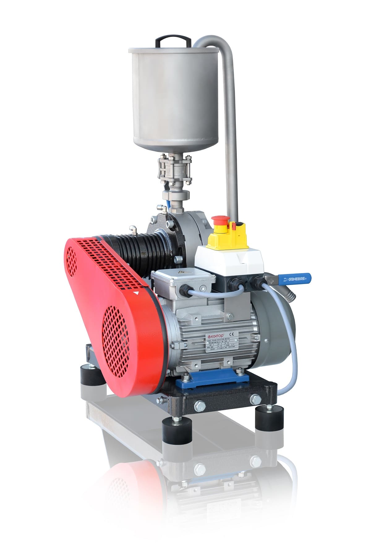
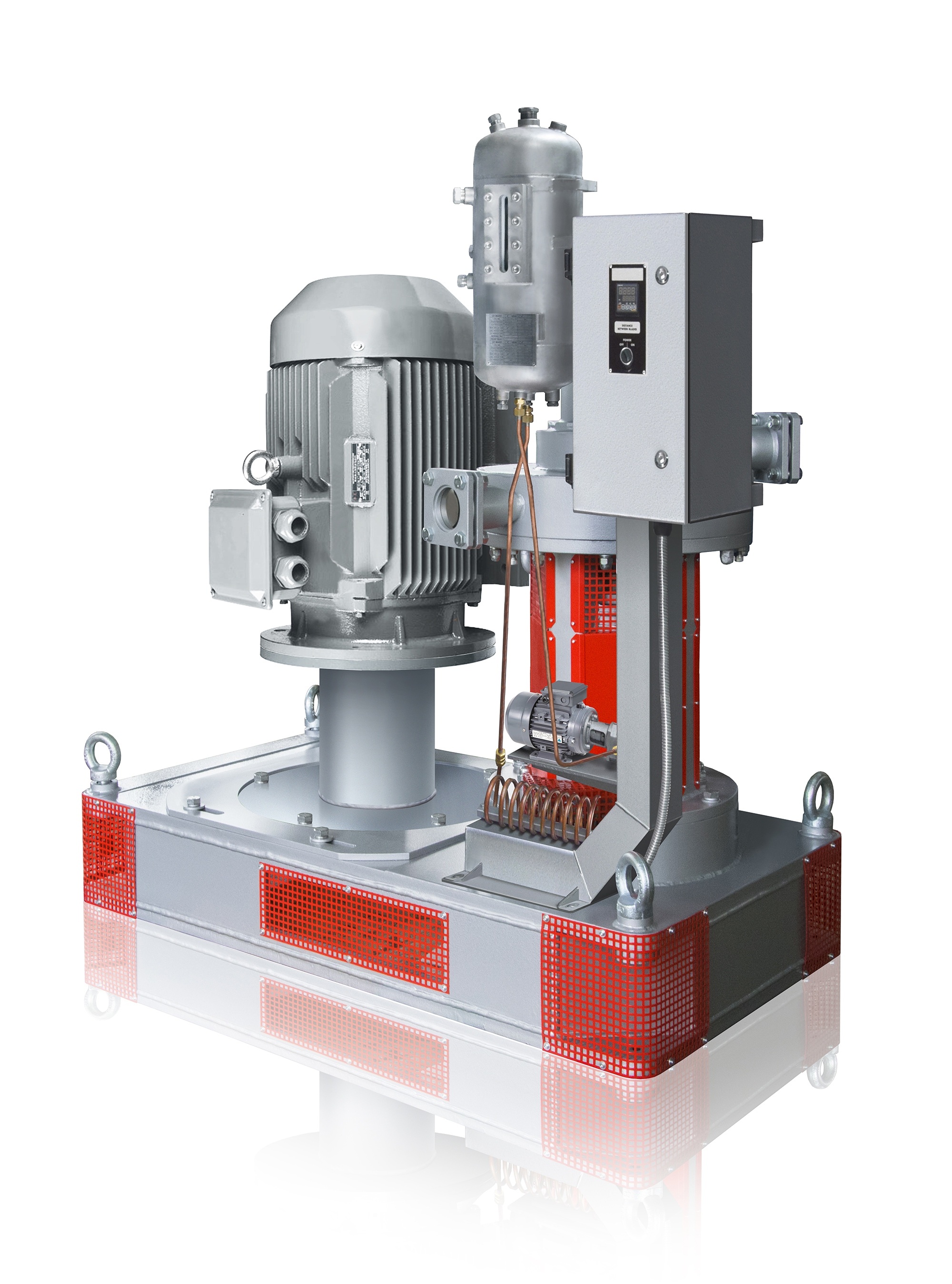
Ferromagnetic particles vortex layer devices use a fundamentally different method of impact on substances compared to ball and hammer mills. The principle of operation of such device can be observed using Figure 1.
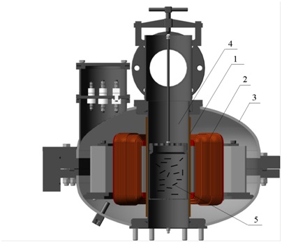
Figure 1 – Device with a vortex layer of ferromagnetic particles (AVS): 1 – protective bushing; 2 – inductor of rotating electromagnetic field; 3 – inductor housing; 4 – operating chamber made of non-magnetic material; 5 – ferromagnetic particles
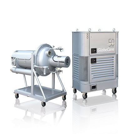
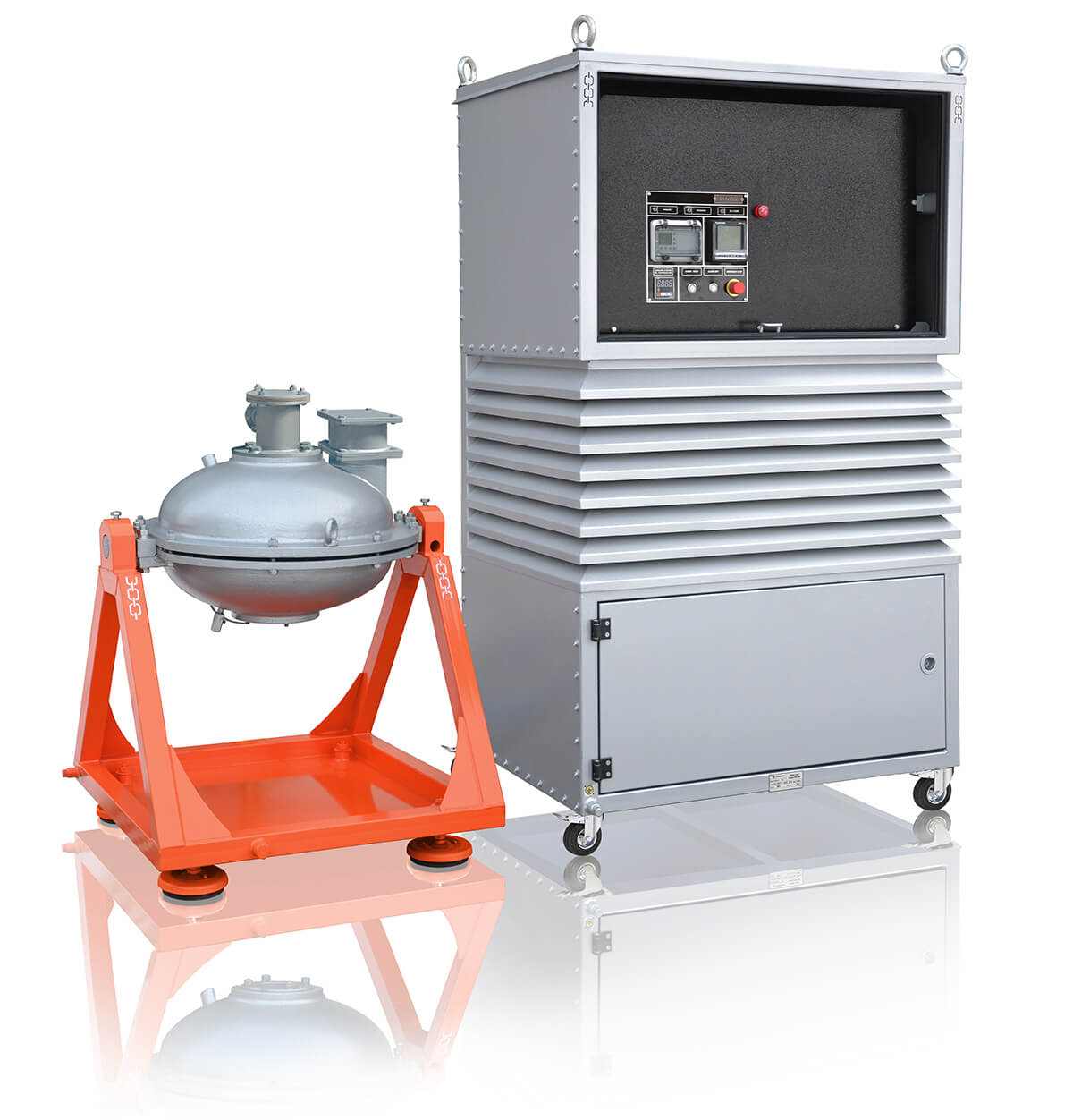
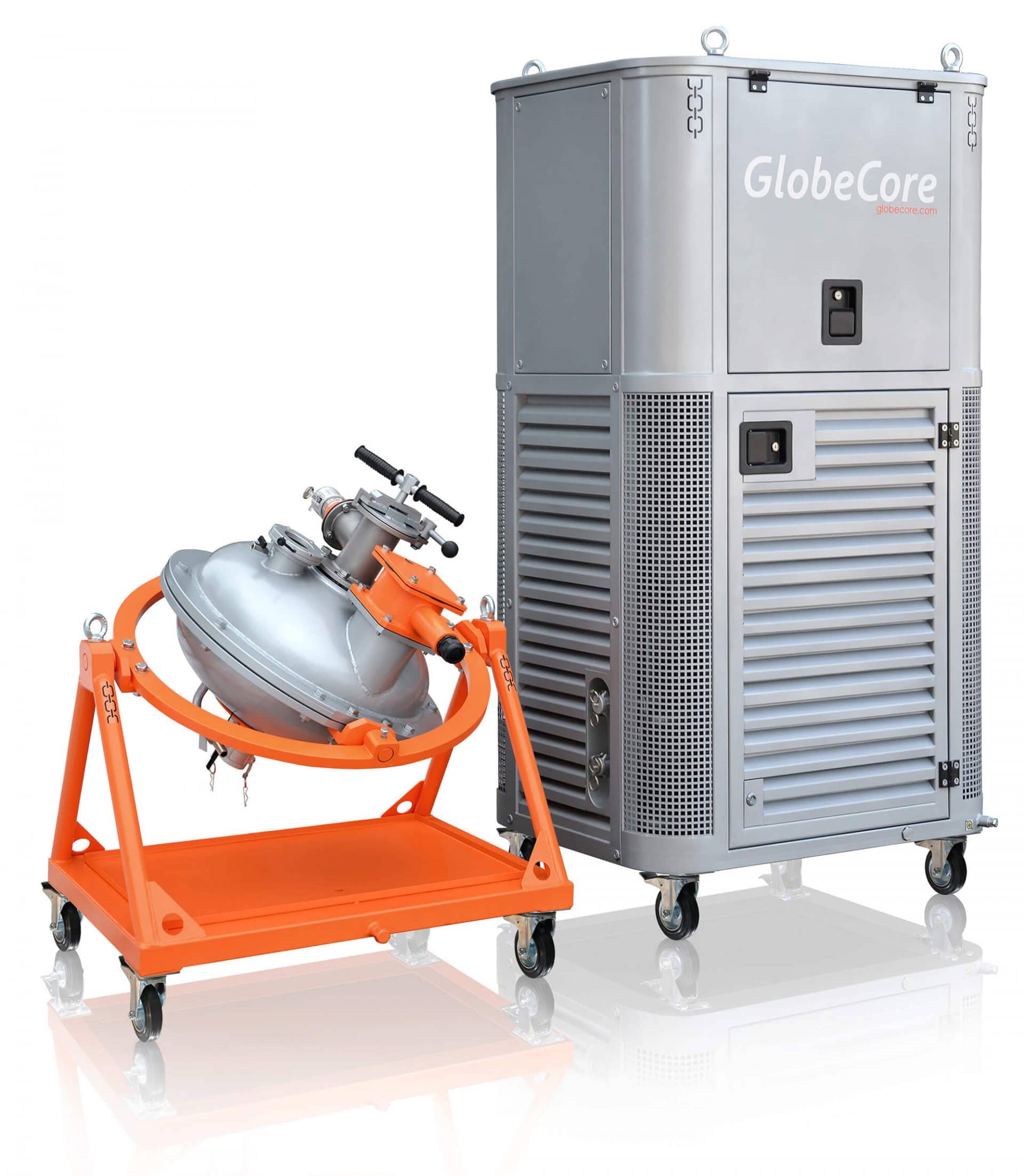
The initial powders of titanium and plutonium dioxides together with ferromagnetic particles 5 are put into a titanium container which is placed in the operating chamber 4 of AVSP-100 device manufactured by GlobeCore. After the device is started, the container performs an axial reciprocating motion. The inductor 2 creates a rotating electromagnetic field which causes ferromagnetic particles to start moving along complex trajectories and to constantly collide with particles of processed powders, with the operating chamber walls, and with one another on their way generating a vortex layer. Meanwhile, several factors influence the processed powders in the operating chamber:
- rotating electromagnetic field;
- direct impacts of ferromagnetic particles;
- acoustic and ultrasonic vibrations resulting from collision of ferromagnetic particles;
- magnetostriction of ferromagnetic particles, etc.
The comprehensive effect of the foregoing factors ensures rapid dispersion and homogenization of initial powders which means that high-quality molding powder is obtained for production of pellets.
Posing hazard to maintenance staff, the input of initial components and ferromagnetic particles, as well as cooling and removing the components are performed automatically.
Advantages of vortex layer devices
The vortex layer devices manufactured by GlobeCore have the following advantages when used in the technological processes of reaction engine fuel production:
- they properly pulverize and mix the initial powdered components ensuring that they are uniformly distributed throughout the pellet;
- they pulverize and mix the components, as well as activate them; the expected result is increased fuel burnup;
- the pellets obtained on the basis of the powders processed in the vortex layer device completely dissolve in nitric acid which is important for regeneration of reaction engine fuel;
- unlike ball and hammer mills, the components are processed in a matter of minutes rather than hours or dozens of hours;
- the devices are compact in size and easy to integrate into the existing process lines of reaction engine fuel production;
- the device can be used in various schemes of nuclear fuel production for fast- and slow-neutron reactors when obtaining finely dispersed powders and homogeneous mixtures.