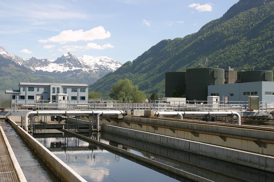
Many world countries experience a shortage, as well as gradual depletion and increasing pollution of fresh water sources. The main cause of surface water pollution is the discharge of untreated and insufficiently treated domestic and industrial wastewater which leads to the unsuitability of receiving water bodies for water use needs. Among highly hazardous types of wastewater, it is worth highlighting the wastewater from light, food-manufacturing, and other industries which contains high concentrations of suspended solids, heavy metal ions, high-molecular-weight organic compounds, fats, surfactants, and other pollutants.
It is the variety of contaminants by concentration and composition that does not allow using one particular method for addressing many treatment tasks. And even if the optimal method is selected, the processes are often not free from disadvantages which are expressed in the long duration of proceeding chemical reactions, overconsumption of chemical agents, low-efficiency use of areas for treatment facilities, high electricity consumption, etc. Thus, the matter of increasing the efficiency of the existing wastewater treatment methods remains relevant.
Principle of operation of an electromagnetic device with a vortex layer of ferromagnetic particles
An electromagnetic device with a vortex layer of ferromagnetic particles is a device consisting of an operating chamber placed in an inductor of a rotating electromagnetic field. The operating chamber contains cylindrical ferromagnetic particles with a certain ratio of length and diameter. Driven by the electromagnetic field, the particles begin to move along complex trajectories generating the so-called vortex layer. A typical design of this kind of device is shown in Figure 1.
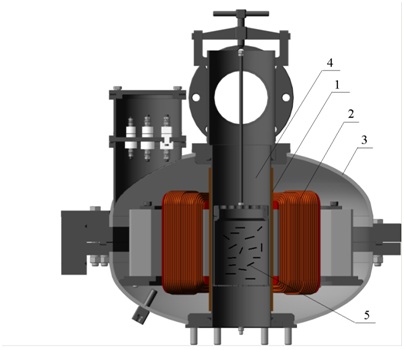
Figure 1 – Device with a vortex layer of ferromagnetic particles: 1 – protective bushing; 2 – inductor of rotating electromagnetic field; 3 – inductor housing; 4 – operating chamber made of non-magnetic material; 5 – ferromagnetic particles
With the design as simple as it seems to be, a number of processes take place in the device operating chamber, and there occur factors the comprehensive effect of which beneficially influences wastewater processing:
- rotating (external) magnetic field;
- numerous interactions of ferromagnetic particles with one another, the operating chamber walls, and processed material;
- acoustic vibrations;
- cavitation;
- electrolysis.
The rapid movement of ferromagnetic particles and cavitation accelerate the course of many physical and chemical reactions. The formation of free hydrogen as a result of water electrolysis considerably activates the reduction reactions. At the same time, the dissociation of water into H + and (OH) provides reasons to assert that the latter can play a significant role in the reactions related to formation of precipitating metal hydroxides.
The combined effects of all the foregoing factors in one operating space simultaneously accelerates almost all the physical and chemical, as well as mechanical and physical reactions a hundred- and thousandfold, and therefore, increases the technological line capacity to the same extent.
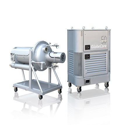
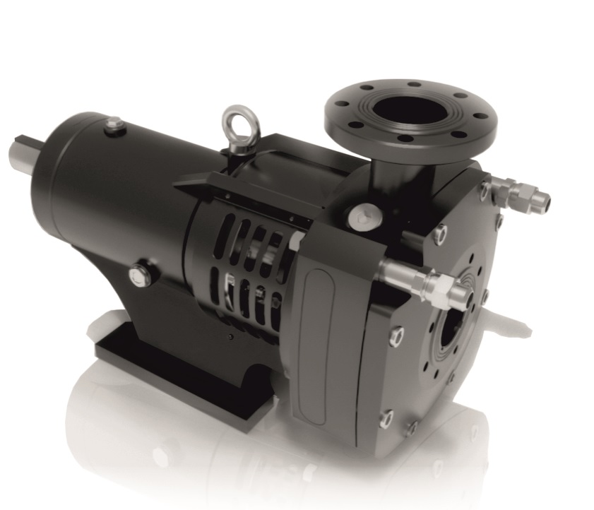
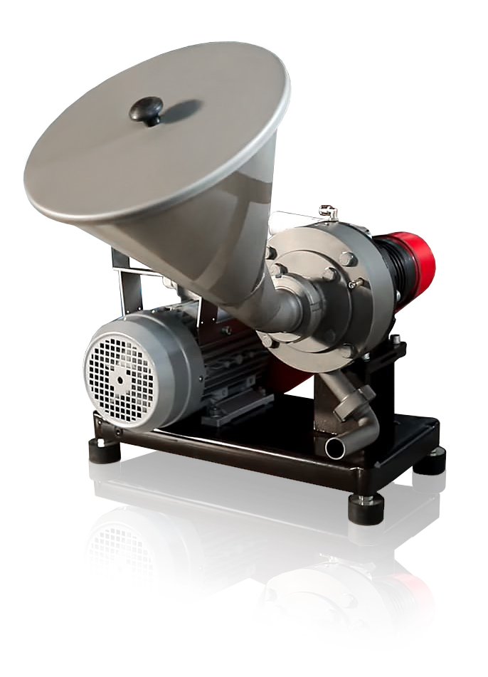
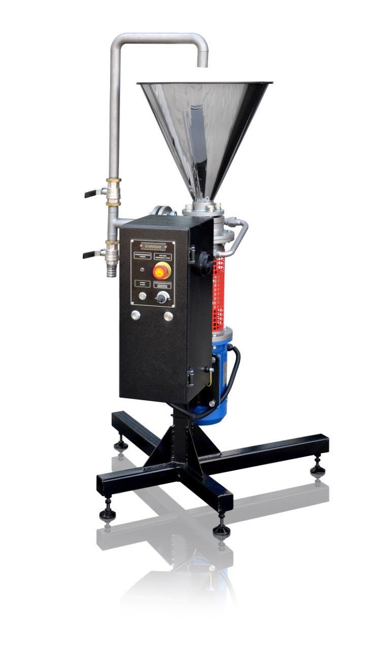
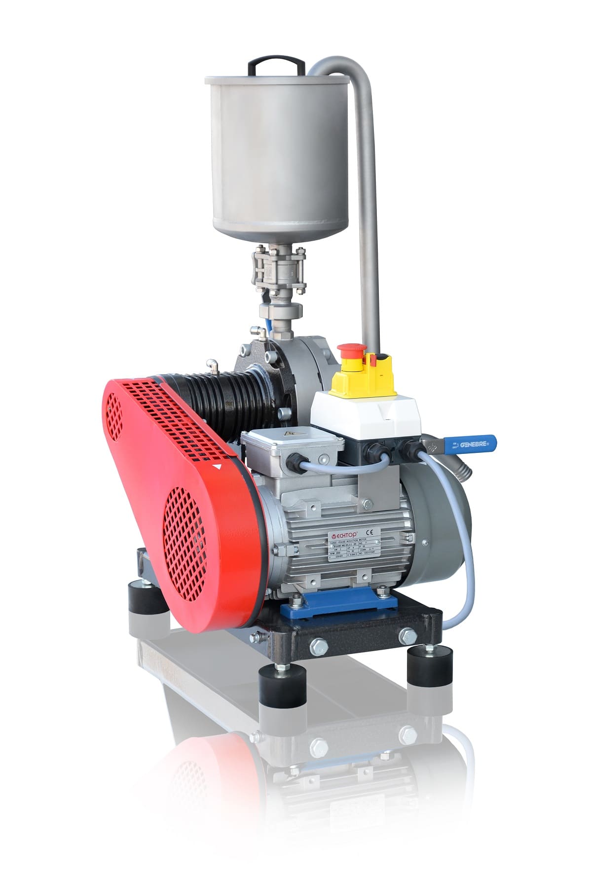
Figure 2 shows AVS-100 vortex layer device manufactured by GlobeCore.
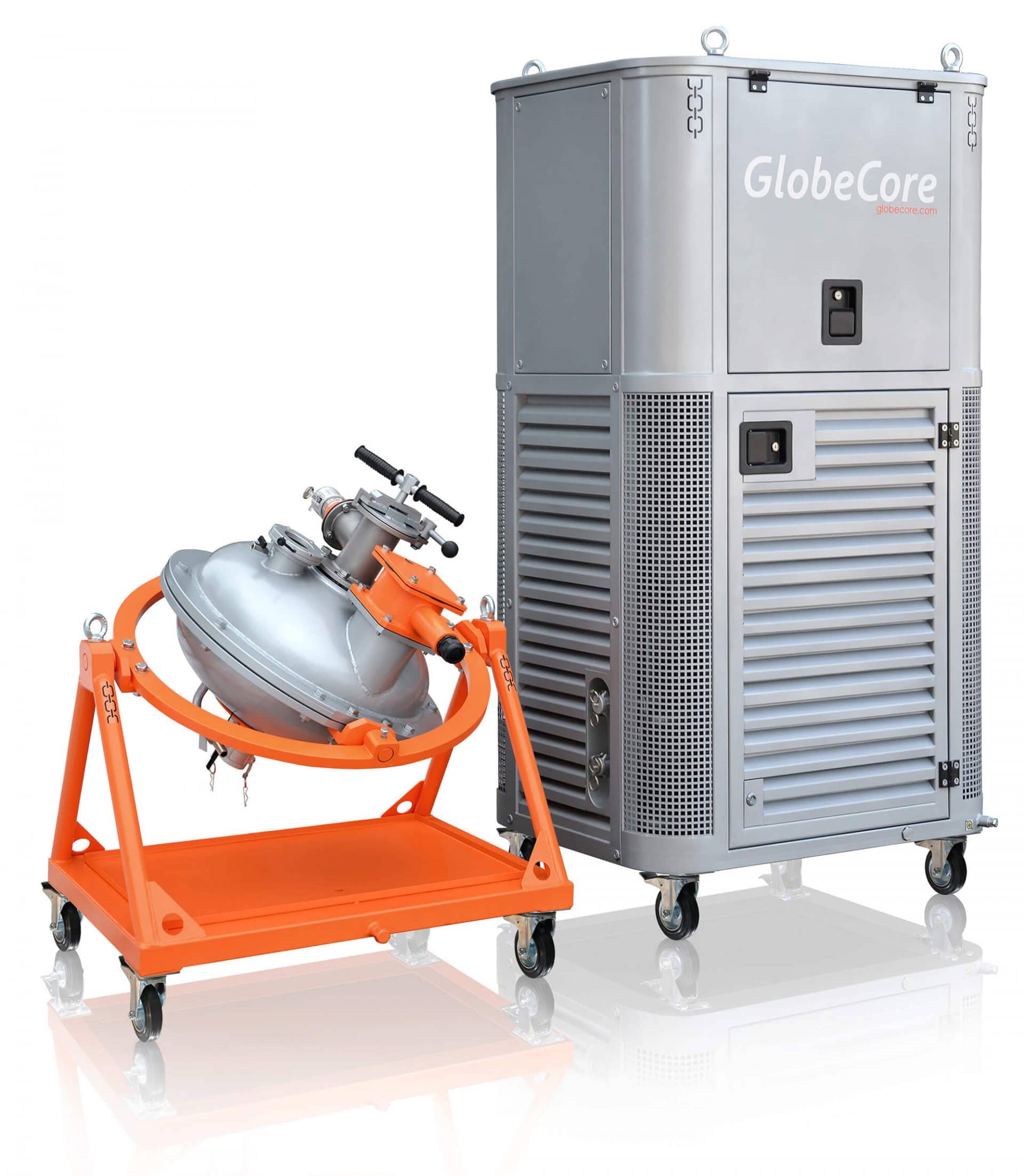
Figure 2 – AVS-100 vortex layer device
Treatment of wastewater containing hexavalent chromium and other heavy metals
The wastewater from galvanizing workshops, chemical, petrochemical, and other industries may contain chromium, nickel, zinc, lead, iron, copper, manganese, and other heavy metals.
There are several methods and process flow diagrams for treating the wastewater of listed types by means of electromagnetic vortex layer devices which makes it possible to considerably reduce the consumption of chemical agents, to achieve more complete treatment, and to render it continuous.
The reduction of hexavalent chromium to trivalent chromium is carried out in an alkaline medium using iron sulfate with simultaneous precipitation of heavy metals in the form of hydroxides. This method is implemented for the wastewater having the Cr+6 concentration of 10–200 mg/L at the wastewater acidity pH = 6 up to several grams and the presence of other heavy metals from 10 to 1,000 mg/L (Figure 3).
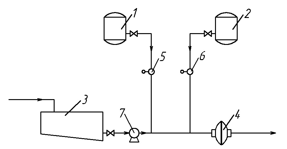
Figure 3 – Process flow diagram of CR+6 reduction in an alkaline medium with simultaneous heavy metals precipitation and wastewater neutralization: 1 — lime slurry tank; 2 — iron sulfate tank; 3 — wastewater collecting and balancing tank; 4 — electromagnetic vortex layer device; 5 — lime slurry batcher; 6 — iron sulfate batcher; 7 — wastewater pump
The results of testing the process flow diagram (Figure 3) in an industrial environment are shown in Table 1. Ca (OH)2 and FeSO4 consumptions were consistent with the stoichiometric calculation.
Table 1 – Wastewater treatment by CR+6 reduction in an alkaline medium with simultaneous heavy metals precipitation in a vortex layer device (ferromagnetic elements: d = 1.6 mm; m = 175 g; before treatment – рН = 2…3, after treatment – рН = 8.5…9)
| Wastewater condition | Treated water condition | |||
| рН | Polluting metals | Concentration of metals, mg/L | Concentration of metals in water after processing in the device, mg/L | рН |
| 2–3 | Cr+6 | 50–100 | 0 | 8.5–9 |
| Cr+3 | 50–100 | 0 | ||
| Fe | up to 500 | traces | ||
| Ni | 50–100 | 0 | ||
| Mg | up to 300 | traces | ||
| Pb | 50–100 | 0.09 | ||
| Cu | 50–100 | traces | ||
The experience of implementing vortex layer devices has shown that it is most expedient to apply the method of reducing Cr+6 to Cr+3 in an alkaline medium with the amount of chromium in the solution not exceeding 200 mg/L, because a large amount of chromium and iron hydroxide precipitates at a greater amount of Cr+3. With a large amount of chromium, the reduction of Cr+6 to Cr+3 using sodium bisulfite in an acidic medium may be recommended as followed by Cr+3 precipitation in an alkaline medium through the use of an electromagnetic vortex layer device at both the first and the second stages (Figure 4).
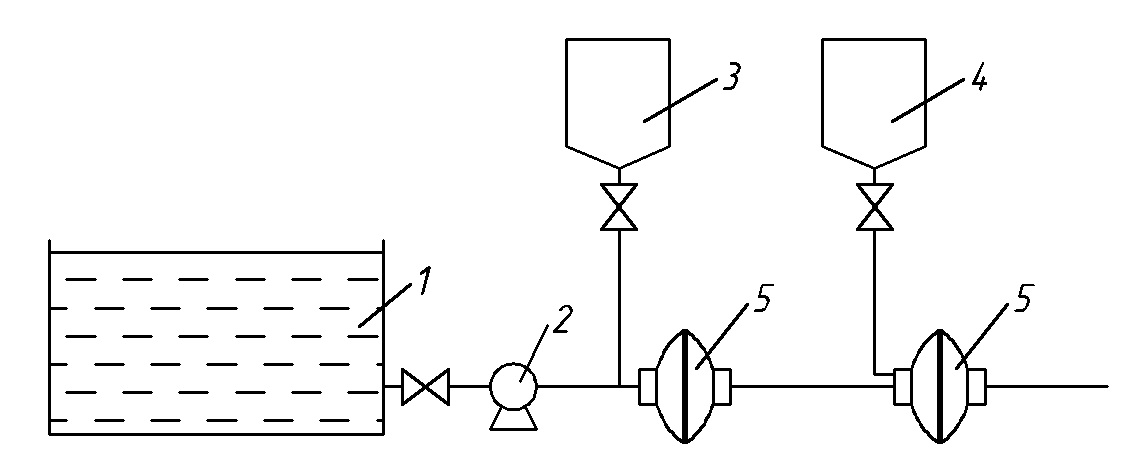
Figure 4. Process flow diagram of Сr+6 reduction followed by precipitation in the form of hydroxide: 1 – wastewater collecting and balancing tank; 2 – wastewater pump; 3 – sodium bisulfite tank; 4 – lime slurry tank; 5 – electromagnetic vortex layer device
Intensified and complete treatment of acid-alkaline wastewater against heavy metal ions with the device involved occurs due to the comprehensive processing of components in a vortex layer as a result of formation of metal hydroxides, precipitation thereof, and sorption of heavy metal ions by iron hydroxide, as well as by means of activated colloid iron which is formed due to dispersion of ferromagnetic elements in the vortex layer and serves as a good reducing agent. Along with its emergence in the vortex layer, hydrogen formation processes occur due to water electrolysis. This feature leads to the influence on the reaction of Cr+6 reproduction and to decreased iron sulfate consumption, as well as to complete reproduction of Cr+6 and other metals contained in wastewater only due to the colloid metal of hydrogen evolution.
Figure 5 shows comparative data of the rate and completeness of Cr+ 6 reduction in the vortex layer device and in the mixing device with different amounts of reducing agent [Logvinenko, 1976]. As it can be seen from the above data, almost complete reduction can be achieved in a vortex layer when the iron sulfate consumption is not more than 30% of the stoichiometric one. The reduction process in the vortex layer is achieved when the processing time of the components is 1 second which makes it possible to carry out a continuous process.
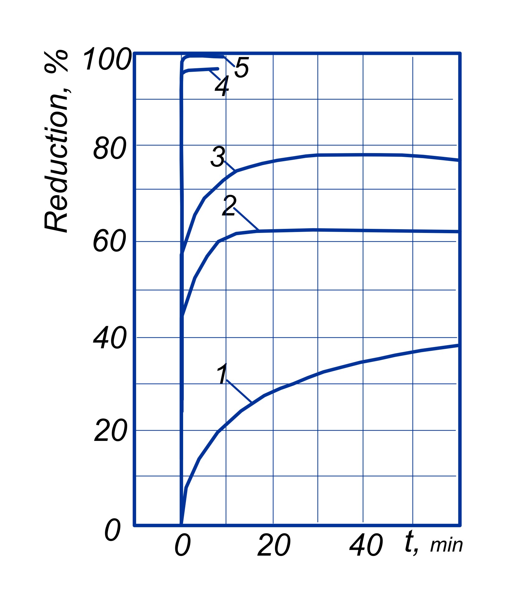
Figure 5. Influence of the processing duration on the process of hexavalent chromium reduction: 1, 2, 3 — in a device containing a mechanical mixer with the FeSO4 consumption equaling 50, 80, and 100% of the stoichiometric one respectively; 4, 5 — in a vortex layer device at the FeSO4 consumption equaling 10 and 30% of the stoichiometric one
The treatment process occurs most efficiently when a lime suspension is used as a chemical agent which is activated when processed in the vortex layer device. The activating effect is confirmed by the IR spectra of CaO of lime milk after processing in a vortex layer which indicates structural and physical changes in the properties of CaO. It allows achieving the degree of treatment to the maximum permissible concentration with the CaO consumption of up to 90–100% of the theoretically required one. At the same time, intensive mixing of the chemical agents, the electromagnetic field action, as well as grinding the obtained compounds leads to the fact that the metal hydroxides obtained after the vortex layer device are more dispersed in comparison to those obtained in the mixing devices (Table 2).
Table 2 – Studying the dispersion ability of metal hydroxides obtained in the mixing and vortex layer devices
| Dispersion ability of hydroxides, micron | Quantitative state of metal hydroxides obtained | |
| in the mixing device, % | in the vortex layer device, % | |
| 100–50 | 1.5 | – |
| 50–30 | 28 | – |
| 30–25 | 25.55 | – |
| 25–30 | 44.95 | – |
| 20–10 | – | – |
| 10–5 | – | 0.31 |
| 5–3 | – | 5.23 |
| 3–2 | – | 28.56 |
| 2–1 | – | 46.9 |
| 1 | – | 19.0 |
Table 2 shows the data of the dispersion ability of the precipitate which was obtained in an industrial environment using a vortex layer device for treating the wastewater which contained a solution of lead salts up to 675 mg/L, iron — 275 mg/L, copper — 68 mg/L, and manganese — 480 mg/L (Logvinenko, 1976). It should be noted that the shown dispersion ability did not lead to deceleration of the precipitation process; instead, the solids precipitation after the vortex layer device occurred 1.5–2 times faster than that after the mixing device. Clarification of the water containing hydroxides occurs at a higher rate due to combined chemical and polarizing coagulation and flocculation.
Treatment of wastewater containing phenol
Vortex layer devices can be effectively used for treating the wastewater from production of phenol-formaldehyde resins, coke-chemical and wood-chemical enterprises which contains phenol, methanol, formaldehyde, and other pollutants. Treatment of wastewater containing phenol is carried out by chemical-based methods which consist in the oxidation of phenol (at the concentration of 0.5–10 g/L) in an acidic medium.
Pyrolusite, potassium or sodium bichromate, ozone, lime chloride, and potassium permanganate can be used as an oxidizing agent. Of the listed chemical agents, potassium or sodium bichromate is recommended for phenol removal in the device at the consumption of 2.5–3.3 g per 1 g of phenol.
In practice, it is recommended to use a water solution of an oxidizing agent with the concentration of 50–200 g/L per Na2Cr2O7 depending on the concentration of phenol, and a 30–50% sulfuric acid solution for acidification.
Reactors with mixers are used for treatment of wastewater containing phenol, and the oxidation process therein takes 3–4 hours at the temperature of 95–100 ºС.
The use of a vortex layer device allows simplifying the process flow diagram to a great extent, reducing the oxidation reaction temperature to 20–40 ºС, and minimizing the process duration which makes it possible to carry out treatment in a continuous mode. The composition of wastewater that can be effectively oxidized in a vortex layer device is shown in Table 3.
Table 3 — Characterization of wastewater from various production facilities where vortex layer devices are used for phenol oxidation
| Pollutants | Amount of pollutants in wastewater from various production facilities, g/L | ||
| Synthesis of phenol-formaldehyde resins | Synthesis of epoxy resin | Synthesis of diphenylolpropane | |
| Н2О4 | – | – | 10 |
| Phenol | 0.5–5 | 0.3–0.5 | 10 |
| Formaldehyde | 2–12 | – | – |
| Diphenylolpropane | 3–5 | 1.5 | 3.3 |
| Methanol | 0.8–10 | 6.0 | – |
The wastewater subjected to treatment using a vortex layer device in a continuous process shall:
- be averaged in terms of composition and pollutant concentration;
- be freed from mechanical impurities;
- contain no resins and petroleum products.
Wastewater treatment using the process flow diagram (Figure 6) is carried out in the following sequence.
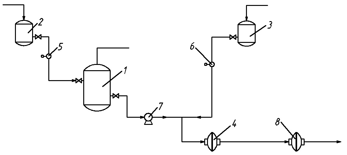
Figure 6. Process flow diagram for removing phenol from industrial wastewater by means of a vortex layer device: 1 – wastewater collecting and balancing tank; 2 – H2SO4 tank; 3 – oxidizing agent tank; 4,8 – vortex layer device; 5, 6 – batchers; 7 – pump
Wastewater enters the collecting and balancing tank 1 where it is averaged, and where the concentration is equalized. If the amount of acid in the wastewater is insufficient, the required amount of sulfuric acid is supplied from the tank 2 using a batcher 5. The wastewater is pumped from the collecting and balancing tank into the electromagnetic vortex layer device in the amount of up to 15 m3/h. As ferromagnetic elements, it uses cylindrical particles with the diameter of 1.2–1.8 mm in the ratio l/d = 10 in the amount of 150–200 g. The running time of such elements is 4–6 hours, after which the elements are changed, or additional input thereof is carried out using an automatic batcher. An oxidizing agent is simultaneously fed into the device where the components are intensively mixed, and the oxidation reaction of phenol and other organic substances (methanol, formaldehyde, etc.) proceeds until water and carbon gas have been formed.
After removal of phenol, wastewater is subjected to reduction of hexavalent chromium which is formed during the oxidation of phenol, as well as neutralization in other vortex layer device (designation 8, Figure 6). Iron sulfate is used for reduction of Cr+6 to Cr+3, and lime milk is used for neutralization.
Treatment of wastewater containing cyanides
The use of electromagnetic vortex layer devices for cyanide wastewater treatment allows carrying out the oxidation of cyanides to cyanates when non-toxic carbonates and ammonia are simultaneously formed. The process takes place in an alkaline medium at pH = 9–10. Lime, soda are used as an alkaline agent in the form of a 5–10% water solution, and a 5–10% solution of lime chloride with calcium hypochlorite or chlorine is used as an oxidizing agent.
The residual amount of cyanide after treatment is 0.005–0.09 mg/L at the initial concentration of 30–350 mg/L.
Important factors that affect the quality of wastewater treatment when using a vortex layer device include:
- selection of the optimal diagram and treatment method;
- selection and layout of process equipment;
- selection of treatment modes;
- monitoring and control of treatment parameters;
- proper use of the devices;
- wastewater averaging, etc.
The efficient use of vortex layer devices and wastewater treatment depends on the degree of its averaging in terms of composition and pollutant concentration which is taken within 1.5–2 hour averaging.
Advantages of vortex layer devices
Electromagnetic vortex layer devices can be effectively used in process flow diagrams of wastewater treatment by chemical-based method with closed use of water at enterprises without discharging it into water bodies. They are used in process flow diagrams of treatment facilities and for carrying out the following processes:
- reduction of hexavalent chromium (Cr+6) to trivalent chromium (Cr+3);
- precipitation of heavy metals (Cr+3, nickel, zinc, lead, copper, cobalt, iron, manganese, etc.);
- neutralization of acid-alkaline effluents;
- oxidation (phenol, cyanogen, petroleum products).