

After 1 month of service and yearly, inspect the gas pressure control components. There is normally an adjustable, three-element, pressure control system for inert gas, which maintains a pressure range of 0.5 to 5 psi in the transformer tank. There is also a bleeder valve that exhausts gas to atmosphere when pressure exceeds relief pressure of the valve, normally 5 to 8 psi.
CAUTION:
The component part descriptions below are for the typical, three-stage pressure regulating equipment supplying inert gas to the transformer. Your particular unit may be different, so check your transformer instruction manual.
High-Pressure Gauge – The high-pressure gauge is attached between the nitrogen cylinder and high-pressure regulator that indicates cylinder pressure. When the cylinder is full, the gauge will read approximately 2,400 psi. Normally, the gauge will be equipped with a low-pressure alarm that activates when the cylinder is getting low (around 500 psi). However, gas will still be supplied, and the regulating equipment will continue to function until the cylinder is empty. Refer to figure 37 for the following descriptions.
High-Pressure Regulator – The high-pressure regulator has two stages. The input of the first stage is connected to the cylinder, and the output of the first stage is connected internally to the input of the second stage. This holds output pressure of the second stage constant. The first stage output is adjustable by a hand-operated lever and can deliver a maximum pressure equal to the pressure in the cylinder (2,400 psi when full) down to zero. The second stage output is varied by turning the adjusting screw, normally adjusted to supply approximately 10 psi to the input of the low-pressure regulator.
Low-Pressure Regulator – The low-pressure regulator is the third stage and controls pressure and flow to the gas space of the transformer. The input of this regulator is connected to the output of the second stage (approximately 10 psi). This regulator is typically set at the factory to supply gas to the transformer at a pressure of approximately 0.5 psi, and it needs no adjustment. If a different pressure is required, the regulator can be adjusted by varying spring tension on the valve diaphragm. Pressure is set at this low value because major pressure changes inside the transformer result from expansion and contraction of oil. The purpose of this gas feed is to make up for small leaks in the tank gaskets and elsewhere so that air cannot enter. Typically, a spring-loaded bleeder for high-pressure relief is built into the regulator and is set at the factory to relieve pressures in excess of 8 psi. The valve will close when pressure drops below the setting, preventing further loss of gas.
Bypass Valve Assembly – The bypass valve assembly opens a bypass line around the low-pressure regulator and allows the second stage of the high-pressure regulator to furnish gas directly to the transformer. The purpose of this assembly is to allow much faster filling/purging of the gas space during initial installation or when the transformer tank needs to be refilled after being opened for inspection.
CAUTION:
During normal operation, the bypass valve must be closed, or pressure in the tank will be too high.
Oil Sump – The oil sump is located at the bottom of the pressure regulating system between the low-pressure regulator and shutoff valve C. The sump collects oil and/or moisture that may have condensed in the low-pressure fill line. The drain plug at the bottom of the sump should be removed before the system is put into operation, as well as once each year during operation, to drain any residual oil in the line. This sump and line will be at the same pressure as the gas space in the top of the transformer. The sump should always be at a safe pressure (less than 10 psi) so the plug can be removed to allow the line to purge a few seconds and blow out the oil. However, always look at the gas space pressure gauge on the transformer or the lowpressure gauge in the nitrogen cabinet, just to be sure, before removing the drain plug.
Shutoff Valves – The shutoff valves are located near the top of the cabinet for the purpose of isolating the transformer tank for shipping or maintenance. These valves are normally of double-seat construction and should be fully opened against the stop to prevent gas leakage around the stem. A shutoff valve is also provided for the purpose of shutting off the nitrogen flow to the transformer tank. This shutoff valve must be closed prior to changing cylinders to keep the gas in the transformer tank from bleeding off.
Sampling and Purge Valve – The sampling and purge valve is normally located in the upper right of the nitrogen cabinet. This valve is typically equipped with a hose fitting; the other side is connected directly to the transformer gas space by copper tubing. This valve is opened while purging the gas space during a new installation or maintenance refill, and it provides a path to exhaust air as the gas space is filled with nitrogen. This valve is also opened when a gas sample is taken from the gas space for analysis. When taking gas samples, the line must be sufficiently purged so that the sample will be from gas above the transformer oil and not just gas in the line. This valve must be tightly closed during normal operation to prevent gas leakage.
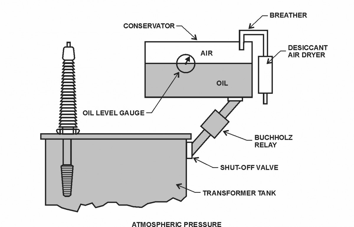
Free Breathing Conservator – This design adds an expansion tank (conservator) above the transformer so that the main tank may be completely filled with oil (figure 38). Oil expansion and air exchange with the atmosphere (breathing) occur away from the oil in the transformer. This design reduces oxygen and moisture contamination because only a small portion of oil is exchanged between the main tank and conservator. An oil/air interface still exists in the conservator, exposing the oil to air. Eventually, oil in the conservator is exchanged with oil in the main tank, and oxygen and other contaminants gain access to the insulation.
If you have transformers of this design, it is recommended that a bladder or diaphragm-type conservator be installed (described below) or retrofitted to the original conservator. In addition, a desiccant-type air dryer should also be installed.
Conservator with Bladder or Diaphragm Design – A conservator with bladder or diaphragm (figure 39) is similar to the design in figure 38 with an added air bladder (balloon) or flat
diaphragm in the conservator. The bladder or diaphragm expands and contracts with the oil and isolates it from the atmosphere. The inside of the bladder or top of the diaphragm is open to atmospheric pressure through a desiccant air dryer. As oil expands and contracts and as atmospheric pressure changes, the bladder or diaphragm “breathes” air in and out. This keeps air and transformer oil essentially at atmospheric pressure. The oil level gauge on the conservator typically is magnetic, like those mentioned earlier, except the float is positioned near the center of the underside of the bladder. With a diaphragm, the level indicator arm rides on top of the diaphragm. Examine the air dryer periodically and change the desiccant when approximately onethird of the material changes color.

Figure 39 – Conservator with Bladder
NOTE:
A vacuum will appear in the transformer if piping between the air dryer and conservator is too small; if the air intake to the dryer is too small, or if the piping is partially blocked. The bladder cannot take in air fast enough when the oil level is decreasing due to rapidly falling temperature. Minimum ¾- to 1-inch piping is recommended. This problem is especially prevalent with transformers that are frequently in and out of service and located in geographic areas with large temperature variations. This situation may allow bubbles to form in the oil and may even activate gas detector relays, such as the Buchholz and/or bladder failure relay. The vacuum may also pull in air around gaskets that are not tight enough or that have deteriorated (which may also cause bubbles) [4].
Conservator Inspection – If atmospheric gases (nitrogen, oxygen, carbon dioxide) and, perhaps, moisture increase suddenly in the DGA, a leak may have developed in the conservator diaphragm or bladder. With the transformer offline and under clearance, open the inspection port on top of the conservator and look inside with a flashlight. If there is a leak, oil will be visible on top of the diaphragm or inside the bladder. Re-close the conservator and replace the bladder or diaphragm at the first opportunity by scheduling an outage. If there is no gas inside the Buchholz relay, the transformer may be re-energized after bleeding the air out of the bladder failure relay. A DGA should be taken immediately to check for oxygen (O2), N2, and moisture. However, the transformer may be operated until a new bladder is installed, keeping a close eye on the DGAs. It is recommended that DGAs be performed every 3 months until the new bladder is installed. After the bladder installation, the oil may need to be de-gassed if O2 exceeds 10,000 parts per million (ppm). Also, carefully check the moisture level in the DGAs to ensure it is below recommended levels for the particular transformer voltage. Check the desiccant in the breather often; never let more than twothirds of the desiccant become discolored before renewing it. All efforts must be made to keep the oxygen level below 2,000 ppm and moisture as low as possible.
Conservator Breather Inspection – Check the dehydrating (desiccant) breather for proper oil level if it is an oiltype unit. Check the color of the desiccant and replace it when approximately one-third remains with the proper color. See figure 40 for a modern oil-type desiccant breather.
Notice the pink desiccant at the bottom of the blue indicating that this portion is water saturated.
Notice also that oil is visible in the very bottom 1 inch or so of the unit. Many times, the oil is clear, and the oil level will not be readily apparent. Normally, there is a thin line around the breather near the bottom of the glass; this indicates where the oil level should be. Compare the oil level with the level indicator line and refill, if necessary. Note the 1¼-inch pipe going from the breather to the conservator. Small tubing (½ inch or so) is not large enough to admit air quickly when the transformer is de-energized in winter. A transformer can cool so quickly that a vacuum can be created from oil shrinkage with enough force to puncture a bladder. When this happens, the bladder is destroyed; and air is pulled into the conservator creating a large bubble.
Bladder Failure (Gas Accumulator) Relay. The bladder failure relay (not on diaphragm-type conservators) (figure 41) is mounted on top of the conservator for the purpose of detecting air bubbles in the oil. The relay will also serve as a backup to the Buchholz relay. If the Buchholz relay overfills with gas and fails to activate an alarm or shut down, gas will bypass the Buchholz and migrate up into the conservator, eventually to the bladder failure relay. Of course, these gases should also show up in the DGA. However, DGAs are normally taken only once per year, and a problem may not be discovered before these alarms are activated. Figure 42 shows a modern relay. Check your transformer instruction manual for specifics because designs vary with manufacturers. No bladder is totally impermeable, and a little air will migrate into the oil.

Figure 40 – Conservator Breather
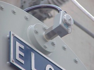
Figure 41 – Photograph of a Bladder Failure Relay
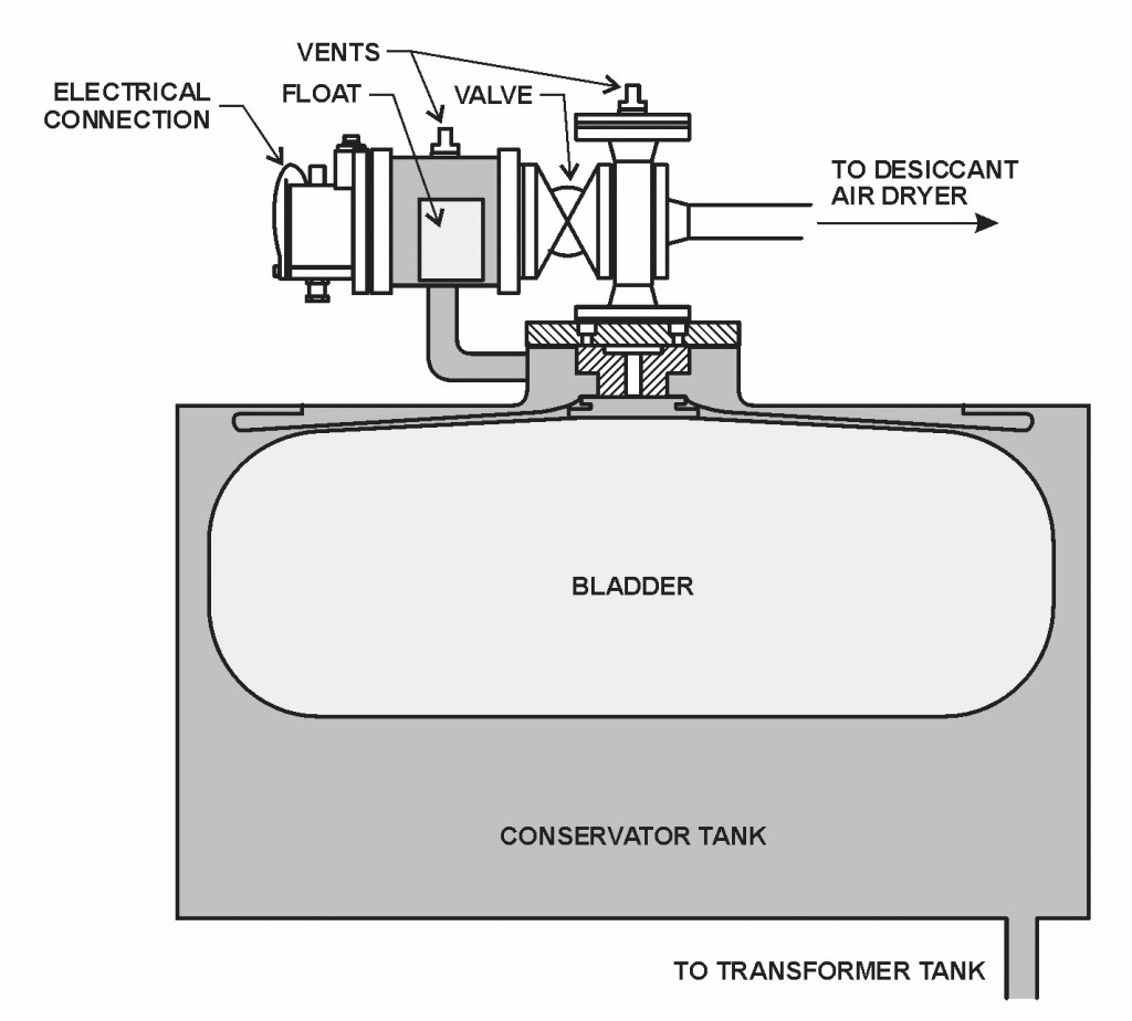
Figure 42 – Bladder Failure Relay
If a hole forms in the bladder, allowing air to migrate into the oil, the relay will detect it. As air rises and enters the relay, oil is displaced and the float drops, activating the alarm. It is similar to the top chamber of a Buchholz relay, since it is filled with oil and contains a float switch.
Every 3 to 5 years usually during Doble testing or if the bladder failure alarm is activated (if the conservator has a diaphragm), place the transformer under clearance and check the Buchholz relay for gas, as mentioned in section 4.7. Open the conservator inspection port and look inside with a flashlight.
Bleed the air/gas from the conservator using the bleed valve on top of the conservator. If the transformer is new and has been in service for only a few months, the problem most likely is air escaping from the structure. With the transformer under clearance, open the inspection port on top of the conservator and look inside the bladder with a flashlight. If oil is found inside the bladder, it has developed a leak; a new one must be ordered and installed.
CAUTION:
Never open the vent of the bladder failure relay unless you have vacuum or pressure equipment available. The oil will fall inside the relay and conservator and pull in air from the outside. You will have to recommission the relay by valving off the conservator and pressurizing the bladder or by placing a vacuum on the relay. See your specific transformer instruction manual for details.
CAUTION:
When the transformer, relay, and bladder are new, some air or gas is normally entrapped in the transformer and piping and takes some time to rise and activate the relay. Do not assume the bladder has failed if the alarm activates within 2 to 3 months after it is put into operation. If this occurs, you will have to recommission the relay with pressure or vacuum. See your specific transformer instruction manual for details. If no more alarms occur, the bladder is intact. If alarms continue, look carefully for oil leaks in the conservator and transformer.
An oil leak is usually also an air leak. This may be checked by looking at the nitrogen and oxygen in the dissolved gas analysis. If these gases are increasing, there is probably a leak; with a sealed conservator, there should be little of these gases in the oil. Nitrogen may be high if the transformer was shipped new and was filled with nitrogen.